| –
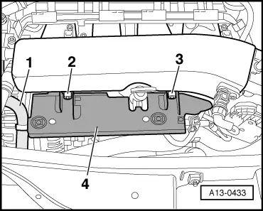
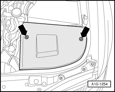
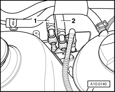
| Remove bolts -2- and -3- and detach retaining plate -4- from dipstick guide tube. |
| –
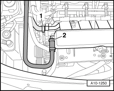
| Disengage coolant hose -1- from retaining plate. |
| –
| Move retaining plate to the side (hoses remain connected). |
| Vehicles with exhaust gas temperature control: |
| –
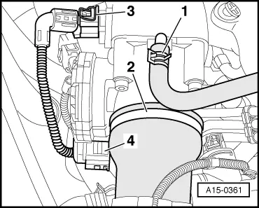
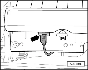
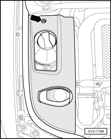
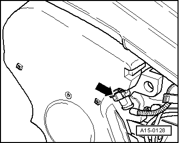
| Unscrew exhaust gas temperature sender 1 -G235- from intake manifold. |
| –
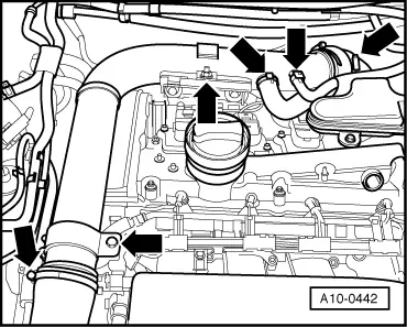
| Detach crankcase breather hose from bottom of intake manifold and move hose clear. |
| –
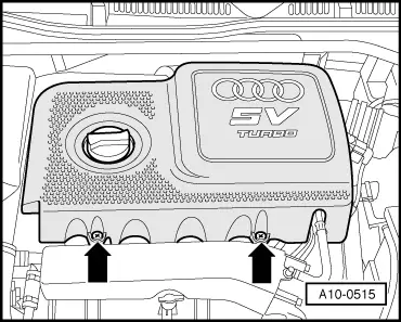
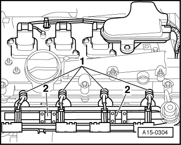
| Unbolt support for intake manifold from intake manifold. |
| –
| Unbolt and remove intake manifold from cylinder head. |

Note | Block off intake ports in cylinder head with clean rags. |
| Installation is carried out in the reverse order; note the following: |
Note | t
| Renew seals and gaskets. |
| t
| Hose connections and hoses for charge air system must be free of oil and grease before assembly. |
| t
| Secure all hose connections with the correct type of hose clips (same as original equipment) → Parts catalogue. |
| t
| When the battery is reconnected, please ensure that the vehicle equipment (e.g. radio, radio/navigation system, clock, electric window lifters) is activated as described in the operating instructions. |
| t
| For further operations after reconnecting power supply, refer to → Rep. Gr.24. |
|
|
|

 WARNING