audi Workshop Repair Guides

Audi Workshop Service and Repair Manuals

Piston and cylinder dimensions > < Sawn conrods
4-cylinder Engine (2-valve), Mechanical Components
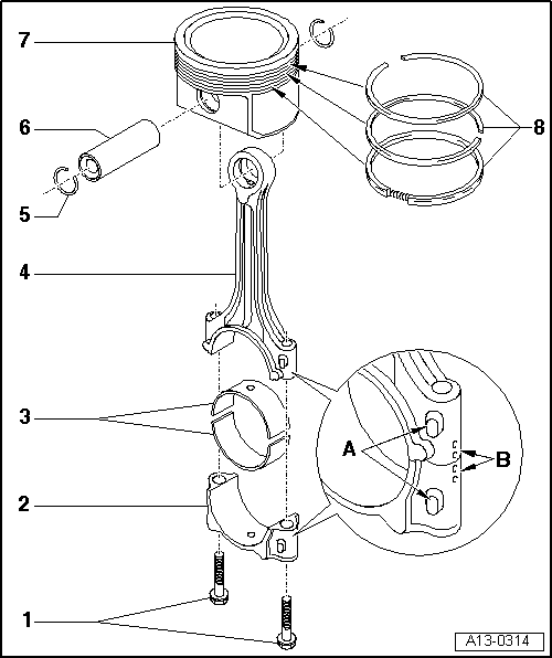
Dismantling and assembling pistons and conrods
Cracked conrods
 
A13-0314

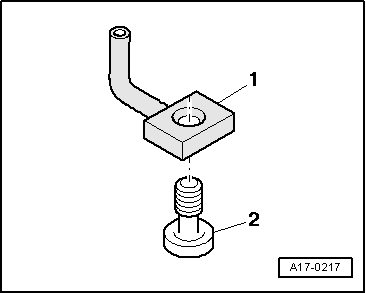
Note:

Oil spray jet and pressure relief valve

=> Fig.13-88

  • Conrod bolt - 30 Nm + 90° (1/4 turn) further
    • ◆ Replace
    • ◆ Oil threads and contact surface
    • ◆ To measure radial play use old bolt
    • ◆ To measure radial play tighten to 30 Nm but no further
  • Conrod bearing cap
    • ◆ Mark cylinder number B
    • ◆ Installation position:
      Markings A face towards pulley side
 
A13-0314
  • Bearing shells
    • ◆ Upper bearing shell with oil bore for piston bolt lubrication
    • ◆ Installation position
      => Fig.13-88
    • ◆ Do not interchange used bearing shells (mark).
    • ◆ Axial play
      New: 0.05...0.31 mm
      Wear limit: 0.37 mm
    • ◆ Check radial play with Plastigage:
      New: 0.01...0.06 mm
      Wear limit: 0.12 mm.
      Do not rotate crankshaft when checking radial play
  • Conrod
    • ◆ Only replace as a set
    • ◆ Mark cylinder number B
    • ◆ Installation position:
      Markings A face towards pulley side
    • ◆ With oil bore for piston pin lubrication
 
A13-0314
  • Circlip
  • Piston pin
    • ◆ If difficult to remove, heat piston to approx. 60 °C.
    • ◆ Remove and install with VW 222a
  • Piston
    • ◆ Checking => Fig.13-87
    • ◆ Mark installation position and cylinder number.
    • ◆ Arrow on piston crown points to pulley end.
    • ◆ Install using piston ring clamp.
    • ◆ Piston and cylinder dimensions
      =>Page 13-89.
  • Piston rings
    • ◆ Offset gaps by 120°
    • ◆ Remove and install with piston ring pliers.
    • ◆ "TOP" must face piston crown.
    • ◆ Checking ring gap
      => Fig.13-86
    • ◆ Checking ring to groove play
      => Fig.13-86
 
V13-0016

→ Fig. 1    Checking piston ring gap

  • ‒ Push ring into cylinder seated squarely on cylinder wall from top down up to approx. 15 mm before bottom edge of cylinder. Use a piston without rings.

Piston ring
Dimensions in mm

New

Wear limit

1st compression ring

0.20...0.40

0.8

2nd compression ring

0.20...0.40

0.8

Oil scraper ring

0.25...0.50

0.8

 
V13-0687

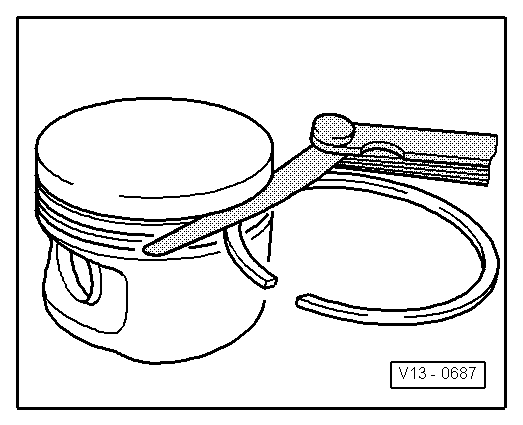
→ Fig. 2    Checking ring to groove play

  • ‒ Clean groove before checking play.

Piston ring
Dimensions in mm

New

Wear limit

1st compression ring

0.06...0.09

0.20

2nd compression ring

0.05...0.08

0.20

Oil scraper ring

0.03...0.06

0.15

 
V13-0010

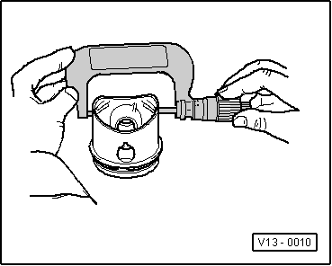
→ Fig. 3    Checking piston

  • ‒ Measure approx. 10 mm from the lower edge, offset by 90° to the piston pin axis.
    • ‒ Permissible deviation from nominal dimension:
      no more than 0.04 mm.

 
V13-0280

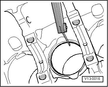
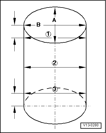
→ Fig. 4    Checking cylinder bores

  • ‒ Measure at three positions diagonally in transverse direction -A- and in longitudinal direction -B- using a 50...100 mm internal dial gauge.
    • ‒ Permissible deviation from nominal dimension:
      no more than 0.08 mm.
 
A13-0360

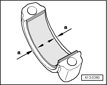
→ Fig.5    Installation position of bearing shell with cracked conrods

  • ‒ Install bearing shells centrally into conrod or into conrod bearing cap.
    • ‒ Dimension a = 3.0 mm

Note:

The bearing shell with the oil bore must be inserted in the conrod.

 
A17-0217

→ Fig.6    Oil spray jet and pressure relief valve

  •     1 -    Oil spray jet (for cooling of piston)
  •     2 -    Bolt with pressure relief valve - 27 Nm

Piston and cylinder dimensions > < Sawn conrods