audi Workshop Repair Guides

Audi Workshop Service and Repair Manuals

Removing and installing exhaust gas recirculation valve -N18 with exhaust gas recirculation potentiometer -G 212 > < Checking adaption of zero position for exhaust gas recirculation valve -N18
4-cylinder Engine (2-valve), Mechanical Components
Exhaust gas recirculation system - vehicles with engine code APF
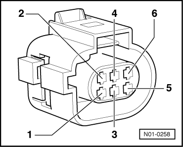
Performing electrical check of exhaust gas recirculation valve -N18 and exhaust gas recirculation potentiometer -G212
 
G24-0023

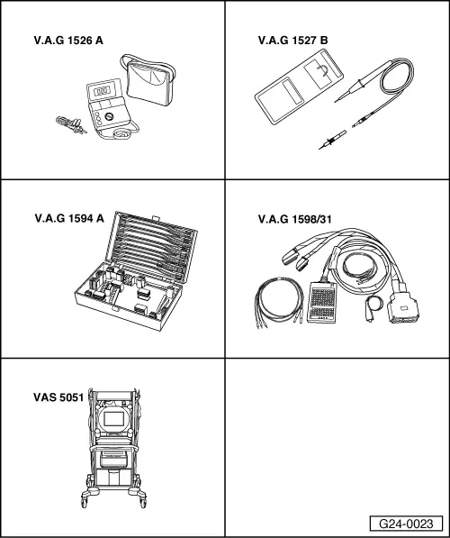
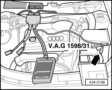
Special tools and workshop equipment required

  • ◆ V.A.G 1526 A
  • ◆ V.A.G 1527 B
  • ◆ V.A.G 1594 A
  • ◆ V.A.G 1598/31
  • ◆ VAS 5051 with VAS 5051/1
 
A10-0885

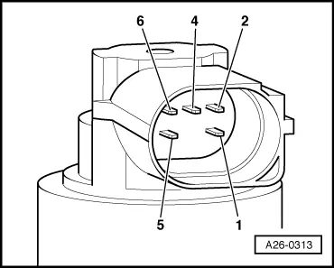
Checking internal resistance

  • ‒ → Remove engine cover -arrows-.

 
A26-0314
  • ‒ → Unplug connector -arrow-.
 
A26-0313
  • ‒ → Connect multimeter as follows to measure resistance:

Component

Connector
Contact

Specified value at room temperature

Exhaust gas recirculation valve -N18

1 + 5

7.5...8.5 ω

Exhaust gas recirculation potentiometer -G212

2 + 4
2 + 6

2.6...4.8 ω
0.5...6.3 ω

If the specifications are not obtained:

  • ‒ Replace the exhaust gas recirculation valve -N18 with exhaust gas recirculation potentiometer -G212 .

If specifications are attained:

Checking voltage supply for exhaust gas recirculation valve -N18

Test requirements:

  • ● Check that power supply relay for Simos control unit -J363 is OK.

=> Simos Fuel Injection and Ignition System; Repair group 28

Note:

The power supply to the exhaust gas recirculation valve is provided by the power supply relay for the Simos control unit -J363.

 
N01-0258
  • ‒ → Connect voltage tester V.A.G 1527 B as follows:

Connector
Contact

Measure to

1

Engine earth

  • ‒ Switch the ignition on.
    • ‒ The LED should illuminate.
  • ‒ Switch ignition off.

If the LED does not illuminate:

  • ‒ Check the wiring from contact 1 of the connector to the power supply relay for Simos control unit -J363 (below cover on left of bulkhead) for open circuit using the current flow diagram.
  • ‒ Eliminate open circuit using the current flow diagram.
 
N01-0258

If the LED illuminates:

Checking voltage supply for exhaust gas recirculation potentiometer -G212

  • ‒ → Connect multimeter between contacts 2 and 4 to measure voltage.
  • ‒ Switch the ignition on.
    • ‒ Specification: 4.5...5.5 V
  • ‒ Switch ignition off.

 
A24-0198

If specification is not attained:

  • ‒ → Connect the V.A.G 1598/31 test box to wiring harness connectors; the engine control unit should not be connected. Attach the earth clip of test box to earth -arrow-.

=> Simos Fuel Injection and Ignition System; Repair group 24

Important
To prevent damage to the electronic components, select appropriate measuring range before connecting the measuring cables and observe the test requirements.
 
N01-0258
  • ‒ → Check for open circuit and short to positive or earth in the following wiring connections:

Connector
Contact

Test box V.A.G 1598/31
Socket

2

96

4

84

  • ‒ Use current flow diagram to eliminate open circuit in wiring/short circuit.

If the wiring is OK:

  • ‒ Replace engine control unit.
 
A24-0198

Checking signal wire between exhaust gas recirculation potentiometer -G212 and engine control unit

  • ‒ → Connect the V.A.G 1598/31 test box to wiring harness connectors; the engine control unit should not be connected. Attach the earth clip of test box to earth -arrow-.

=> Simos Fuel Injection and Ignition System; Repair group 24

Important
To prevent damage to the electronic components, select appropriate measuring range before connecting the measuring cables and observe the test requirements.

 
N01-0258
  • ‒ → Check for open circuit and short to positive or earth in the following wiring connection:

Connector
Contact

Test box V.A.G 1598/31
Socket

6

108

  • ‒ Use current flow diagram to eliminate open circuit in wiring/short circuit.
 
N01-0258

Checking actuation of exhaust gas recirculation valve -N18

Test requirements:

  • ● Power supply OK.
  • ‒ → Connect voltage tester V.A.G 1527 B to contacts 1 and 5 of the connector.
  • ‒ Connect vehicle diagnostic, testing and information system VAS 5051 and select vehicle system "01 - Engine electronics". For this purpose, the ignition must be switched on.

=> Simos Fuel Injection and Ignition System; Repair group 01

 
A01-0122

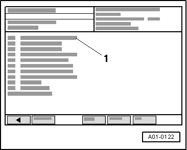
→ Display on VAS 5051:

  • ‒ Under -1- select the diagnostic function "03 - Final control diagnosis".
  • ‒ Actuate the exhaust gas recirculation valve -N18.
    • ‒ The LED must flash slowly.

Note:

Voltage testers with a low current consumption continue to glow faintly between actuation from the engine control unit (rather than extinguishing completely) and become much brighter when actuated.

  • ‒ Exit function "03 - Final control diagnosis" by pressing the ◂ key.
  • ‒ Press "06 - End output".
  • ‒ Switch ignition off.
 
A24-0198

If LED does not flash:

  • ‒ → Connect the V.A.G 1598/31 test box to wiring harness connectors; the engine control unit should not be connected. Attach the earth clip of test box to earth -arrow-.

=> Simos Fuel Injection and Ignition System; Repair group 24

Important
To prevent damage to the electronic components, select appropriate measuring range before connecting the measuring cables and observe the test requirements.
 
N01-0258
  • ‒ → Check for open circuit and short to positive or earth in the following wiring connection:

Connector
Contact

Test box V.A.G 1598/31
Socket

5

115

  • ‒ Use current flow diagram to eliminate open circuit in wiring/short circuit.

If the wiring is OK:

  • ‒ Replace engine control unit.

Removing and installing exhaust gas recirculation valve -N18 with exhaust gas recirculation potentiometer -G 212 > < Checking adaption of zero position for exhaust gas recirculation valve -N18