audi Workshop Repair Guides

Audi Workshop Service and Repair Manuals

Removing and installing map-controlled engine cooling thermostat > < Checking thermostat for map-controlled engine cooling system
Checking coolant temperature sender - radiator outletG83
Checking coolant temperature sender - radiator outlet -G83-
Special tools and workshop equipment required
   
t  Hand-held multimeter -V.A.G 1526 B-
  W00-10023
t  Auxiliary measuring set -V.A.G 1594 C-
Test sequence
Fitting location: Bottom left of radiator.
  Note
Checking coolant temperature sender -G62- → Rep. Gr.28.
–  Unplug electrical connector at coolant temperature sender - radiator outlet -G83-.
–  Connect multimeter (resistance measurement range) to sender.
  W00-10008
Examples:
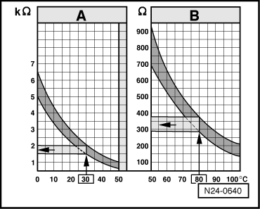
Area -A- shows the resistance values for the temperature range 0 … 50 °C, area -B- the values for the temperature range 50 … 100 °C.
t  30 °C is measured in range -A- and corresponds to a resistance of 1.5 .. 2.0 kΩ.
t  80 °C is measured in range -B- and corresponds to a resistance of 275 .. 375 Ω.
If specification is not obtained:
–  Renew coolant temperature sender - radiator outlet -G83-.
If reading matches specification:
–  Switch off ignition.
–  Connect adapter cable, 121-pin -V.A.G 1598/31- (test box) to connectors of wiring harness; do not connect engine control unit. Connect earth clip of test box to earth → Rep. Gr.24.
  Caution
To avoid damage to the electronic components, select the required measuring range and observe test conditions before connecting the test leads.
  N24-0640
–  Check for open circuit and short to positive or earth in the following wiring:
  A24-0331
Connector
Contact
Adapter cable, 121-pin -V.A.G 1598/31- (test box)
Socket
-1-25
-2-47

–  Repair wiring connection if necessary.
   

Removing and installing map-controlled engine cooling thermostat > < Checking thermostat for map-controlled engine cooling system