audi Workshop Repair Guides

Audi Workshop Service and Repair Manuals

Securing engine to assembly stand > < Removing and installing engine
4-Cylinder engine (2-valve, roller rockers), Mechanics
Removing and installing engine
Notes on removing

Note:

Check whether a coded radio is installed as during the forthcoming work sequences the battery earth strap must be disconnected. Obtain radio code first if necessary.

  • ‒ The engine is removed upwards together with the gearbox.
  • ‒ With ignition switched off disconnect battery earth strap.
  • ‒ All cable ties which are opened or cut open when removing engine, must be replaced in the same position when installing engine.
  • ‒ Remove air cleaner housing:

=> Repair group 24; Servicing injection system; Removing and installing air cleaner

 
A10-0116
  • ‒ → Remove battery and battery retainer.

Warning!
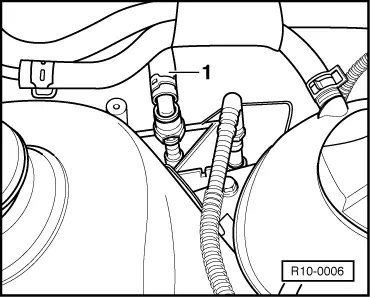
Fuel supply lines are under pressure! Before removing from hose connection wrap a cloth around the connection. Then release pressure by carefully pulling hose off connection.

 
R10-0006
  • ‒ → Now separate fuel supply pipe 1 (press release button).
  • ‒ Pull hose off solenoid valve 1 (N80) at intake manifold.
  • ‒ Seal the pipes so that the fuel system is not contaminated by dirt etc.
  • ‒ Observe rules for cleanliness .
  • ‒ Loosen or separate the following components:
    • ‒ The vacuum hose from inlet manifold to brake servo
    • ‒ The connector from engine speed sender and from intake manifold pressure sender or intake air temperature sender
    • ‒ The connector from ignition transformer, from Hall sender and throttle valve control part
    • ‒ The connector from coolant temperature sender and from oil pressure switch
    • ‒ Injector connectors
    • ‒ Lambda probe connector
    • ‒ The 2-pin connector from knock sensor (rear of cylinder block)
  • ‒ Disconnect all electric wires from gearbox, alternator and starter and move clear.
  • ‒ Pull off/disconnect all other electrical connections as necessary from engine and lay to one side.
  • ‒ Pull vacuum and breather hoses off engine.
  • ‒ Remove noise insulation tray:

=> General body repairs, exterior; Repair group 50; Front body; Noise insulation - Assembly overview

Vehicles with drive unit protection plate

  • ‒ Remove drive unit protection plate

=> General body repairs, exterior; Repair group 50; Front body; Noise insulation - Assembly overview

Continuation for all vehicles

  • ‒ Disconnect selector mechanism from gearbox.

=> 5-Speed manual gearbox 02T; Repair group 34; Servicing selector mechanism

  • ‒ Remove hydraulic clutch slave cylinder:

=> 5-Speed manual gearbox 02T; Repair group 30; Servicing clutch mechanism

Note:

Clutch pedal must not be depressed.

  • ‒ Loosen belt pulley securing bolts from power steering vane pump.
  • ‒ Remove ribbed belt => Page 13-9.
  • ‒ Remove securing clamps for power steering pressure pipe.
  • ‒ Unbolt power steering vane pump and secure to sub-frame with wire; hoses remain connected:

=> Running gear, axles, steering; Repair group 48; Assembly overview: vane pump, reservoir, hydraulic pipes; Removing and installing power steering vane pump.

  • ‒ Open and close the expansion tank sealing cap to release pressure in cooling system.
  • ‒ Drain coolant.
  • ‒ Pull off coolant hose at engine with assembly tool for spring-type clamps VAS 5024.

Vehicles with air conditioner

 
A37-0200
  • ‒ Removing air conditioner compressor:

=> Heating, Air conditioning; Repair group 87; removing and installing compressor bracket

  • ‒ Observe additional notes and assembly work

Continuation for all vehicles

  • ‒ → Disconnect pendulum support -arrows-.
  • ‒ Separate front exhaust pipe from exhaust manifold => Page 26-2, exhaust manifold, front exhaust pipe and catalytic converter with attachments.
  • ‒ Remove left and right-hand drive shaft on gearbox and tie up:
 
R10-0002

=> Running gear, axles, steering; Repair group 40; Removing and installing drive shaft
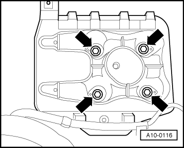
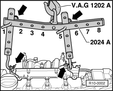
  • ‒ → Attach lifting tackle 2024 A as follows and lift slightly with workshop crane:

    Pulley end:
    3rd hole in hook at position 1

    Flywheel end:
    3rd hole in hook at position 5

Warning!
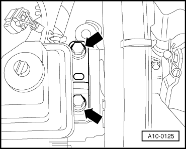
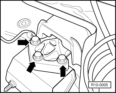
The hooks and locating pins must be secured with locking pins -arrows-.

Notes:

  • ◆ The positions marked 1...4 on the bar must be towards the pulley end.
  • ◆ The holes in the hook rails are counted up from the hook.
 
A10-0125
  • ‒ → Unbolt engine side of assembly mounting from engine bracket -arrows-.
 
R10-0005
  • ‒ → Unbolt gearbox side of assembly mounting from gearbox bracket -arrows-.

Turn assembly slightly to left (engine forwards, gearbox rearwards) and lift out engine carefully.

Note:

When the assembly is lifted off, it must be carefully guided to prevent damage to the bodywork.

Securing engine to assembly stand > < Removing and installing engine