audi Workshop Repair Guides

Audi Workshop Service and Repair Manuals

Coolant hose connection diagram > < Parts of cooling system (on body)
4-Cylinder engine (2-valve, roller rockers), Mechanics
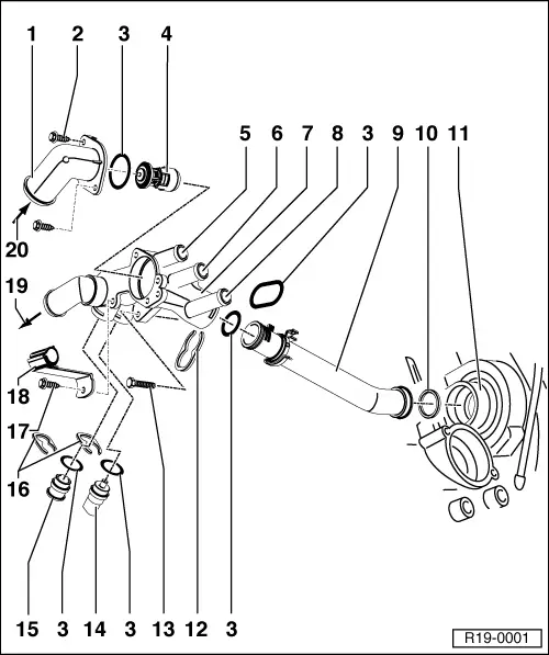
Removing and installing parts of cooling system
Parts of cooling system (on engine)
 
R19-0001
  • Connection
  • Self-tapping bolt, 9 Nm
  • O-ring
    • ◆ Renew
  • Coolant thermostat
    • ◆ Checking operation: heat-up thermostat in water the thermo element pin must move out
    • ◆ Temperature check: Opening starts (approx. 84 °C) and ends (approx. 98 °C) cannot be checked.
  • To heat exchanger
    • ◆ Coolant hose connection diagram
 
R19-0001
  • From expansion tank
    • ◆ Coolant hose connection diagram => Page 19-13
  • Thermostat housing
  • From heat exchanger
    • ◆ Coolant hose connection diagram => Page 19-13
  • Coolant pipe
    • ◆ Coolant hose connection diagram => Page 19-13
  • Seal
    • ◆ Renew
  • Coolant pump housing on cylinder block
  • Retaining clip
    • ◆ Check for secure seating
  • 10 Nm
 
R19-0001
  • Coolant temperature sender (G62)
    • ◆ With coolant temperature gauge sender (G2)
    • ◆ For engine control unit
    • ◆ If necessary release pressure in cooling system before removing
    • ◆ Checking:

=> Repair Group 01; Fault memory; Interrogating and erasing fault memory of engine control unit

  • Sealing plug
    • ◆ If necessary release pressure in cooling system before removing
  • Retaining clip
    • ◆ Check for secure seating
  • Self-tapping bolt
  • Bracket
  • To bottom of radiator
    • ◆ Coolant hose connection diagram => Page 19-13
 
R19-0001
  • From top of radiator
    • ◆ Coolant hose connection diagram => Page 19-13
 
R19-0004

Coolant pump side

  • Coolant pump
    • ◆ With integrated seal
    • ◆ Seal must not be separated from coolant pump
    • ◆ Replace damaged or leaking coolant pump together with seal
    • ◆ Check for ease of movement
    • ◆ Removing and installing
      => Page 19-23
  • Rear toothed belt guard
  • Camshaft sprocket
    • ◆ When installing note fixing arrangement
    • ◆ Note position when installing the toothed belt
      => Page 15-11
 
R19-0004
  • 20 Nm + 1/4 turn (90 °) further
    • ◆ Renew
    • ◆ To loosen and tighten, hold with retainer 3036
  • Toothed belt
    • ◆ Mark D.O.R. before removing
    • ◆ Check for wear
    • ◆ Do not kink
    • ◆ Removing, installing and tensioning
      => Page 15-11
  • Toothed belt guard - upper part
  • 10 Nm
  • Toothed belt guard - lower part
  • 10 Nm
    • ◆ Install with D6
  • 20 Nm

Coolant hose connection diagram > < Parts of cooling system (on body)