
A3 Mk1
|
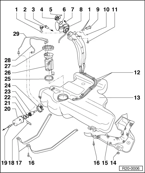
Removing and installing parts of fuel supply system
Removing and installing fuel tank with its attachments and fuel filter
|
 |
|
|
|
|
|
|
=> Repair group 24; Servicing injection system; Removing and installing parts of injection system |
|
|
|
 |
|
|
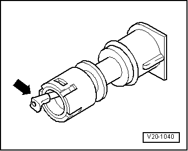
→ Fig. 2 Checking vent valve Lever in rest position: Closed Lever pushed in direction of arrow: Open Note: Before installing vent valve remove fuel tank cap. |