audi Workshop Repair Guides

Audi Workshop Service and Repair Manuals

Piston and cylinder dimensions > < Sawn conrods
4-Cylinder engine (5-valve), Mechanics
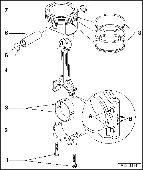
Dismantling and assembling pistons and conrods
Cracked-steel conrods
 
A13-0314

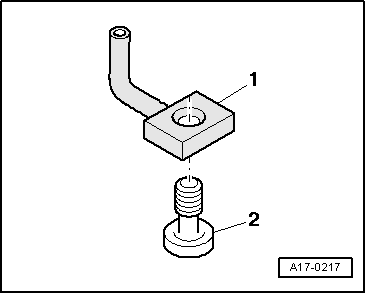
Note:

Oil spray jet and oil pressure relief valve

=> Fig. 13-85

  • Conrod bolt, 30 Nm + 1/4 turn (90 °) further
    • ◆ Renew
    • ◆ Oil threads and contact surface
    • ◆ To measure radial clearance use old bolts
    • ◆ To measure radial clearance tighten to 30 Nm but not further
 
A13-0314
  • Conrod bearing cap
    • ◆ Mark cylinder number -B-
    • ◆ Installation position:
      Marking -A- faces towards pulley end
  • Bearing shells
    • ◆ Upper bearing shell with oil drilling for piston pin lubrication
    • ◆ Note installation position
      =>Fig.13-85
    • ◆ Do not interchange used bearing shells (mark)
    • ◆ Axial clearance
      New: 0.10...0.35 mm
      Wear limit: 0.40 mm
    • ◆ Check radial clearance with
      Plastigage:
      New: 0.01...0.05 mm
      Wear limit: 0.12 mm
      Do not rotate crankshaft when checking radial clearance
 
A13-0314
  • Conrod
    • ◆ Only renew as a set
    • ◆ Mark cylinder number -B-
    • ◆ Installation position:
      Marking -A- faces towards pulley end
    • ◆ With oil drilling for piston pin lubrication
  • Circlip
  • Piston pin
    • ◆ If difficult to move, heat piston to approx. 60 °C
    • ◆ Remove and install with VW 222a
 
A13-0314
  • Piston
    • ◆ Checking => Fig. 13-84
    • ◆ Mark installation position and cylinder number
    • ◆ Arrow on piston crown points to pulley end
    • ◆ Install using piston ring clamp
    • ◆ Piston and cylinder dimensions
      =>Page 13-86
  • Piston rings
    • ◆ Offset gaps by 120 °
    • ◆ Remove and install with piston ring pliers
    • ◆ "TOP" must face towards piston crown
    • ◆ Checking ring gap
      => Fig. 13-83
    • ◆ Checking ring to groove clearance
      => Fig. 13-83
 
V13-0016

→ Fig. 1    Checking piston ring gap

  • ‒ Push ring squarely from above down to approx. 15 mm from bottom end of cylinder. To do this use a piston without rings.

Piston ring
Dimension in mm

New

Wear limit

1st compression ring

0.20...0.40

0.8

2nd compression ring

0.20...0.40

0.8

Oil scraper ring

0.25...0.50

0.8

 
V13-0687

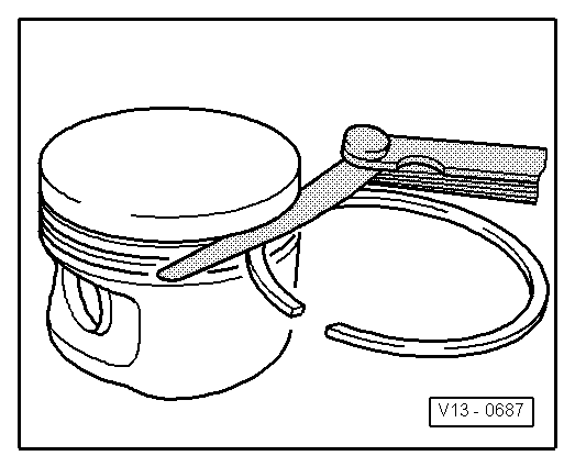
→ Fig. 2    Checking ring to groove clearance

  • ‒ Clean groove before checking clearance.

Piston ring
Dimension in mm

New

Wear limit

1st compression ring

0.06...0.09

0.20

2nd compression ring

0.05...0.08

0.20

Oil scraper ring

0.03...0.06

0.15

 
V13-0010

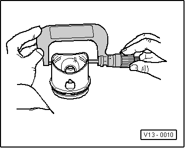
→ Fig. 3    Checking piston

  • ‒ Measure pistons approx. 10 mm from lower edge of skirt, at 90° to the piston pin axis.
    • ‒ Deviation from nominal dimension
      not more than 0.04 mm

 
V13-0280

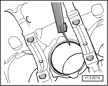
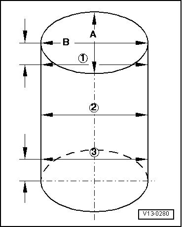
→ Fig. 4    Checking cylinder bores

Special tools and workshop equipment required

  • ◆ Internal dial gauge 50...100 mm
  • ‒ Take measurements at 3 positions in both lateral -A- and longitudinal -B- directions.
    • ‒ Deviation from nominal dimension
      not more than 0.08 mm
 
A13-0360

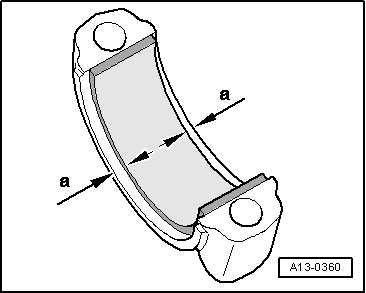
→ Fig.5    Bearing shell installation position with cracked-steel conrods

  • ‒ Insert bearing shell centrally in conrod or conrod bearing cap.
    • ‒ Dimension a = 3.0 mm

 
A17-0217

→ Fig.6    Oil spray jet and pressure relief valve

  •     1 -    Oil spray jet (for piston cooling)
  •     2 -    Bolt with pressure relief valve - 27 Nm
    • ‒ Engines with sawn conrods:
      Opening pressure 2.5 ... 3.2 bar
    • ‒ Engines with cracked-steel conrods:
      Opening pressure 1.3 ... 1.6 bar

Piston and cylinder dimensions > < Sawn conrods