audi Workshop Repair Guides

Audi Workshop Service and Repair Manuals

Checking engine speed signal > < Checking vehicle speed signal
Diesel Direct Injection and Glow Plug System (TDI 4 cyl.) >07.99
Checking auxiliary signals
Testing Cruise Control System (CCS)

The CCS has no components of its own (except for operating switch). All CCS functions are performed by diesel direct injection system.

  • ‒ Read measured value block, display group 06, engine at idling speed
 
→ Indicated on display:
Read measured value block 6    ⇒
    0 km/h    0    0    0    000000    0
  • ‒ Check display in display zone 4.
 
→ Specification: 0
Read measured value block 6    ⇒
    0 km/h    0    0    0    000000    0

 
→ If the value 255 is displayed in display zone 4:
Read measured value block 6    ⇒
    0 km/h    255    0    0    000000    0
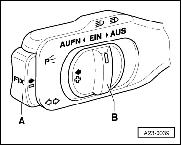
  • ‒ Activate cruise control system
    .

Only for vehicles with automatic gearbox:

  • ‒ Take vehicle for a test drive and go beyond a speed of 30 km/h once. After completing the test drive, leave the engine running and engage the selector lever in position 2, 3 or D.
  • ‒ Apply handbrake.

Note:

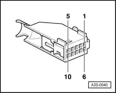
On vehicles with automatic transmission the voltage supply for the CCS switch is only supplied at speeds above 30 km/h and with selector lever in position 2, 3 or D. The power supply is then retained even when idling as long as a driving position is engaged (not 1 or R).

 
→ Test display in display zone 3.
Read measured value block 6    ⇒
    0 km/h    0    0    0    000000    0

 
A23-0039

Test conditions

Display zone 3

Switch B in "OFF" position

000000

Switch B in "OFF/AUS" position but before engagement point

000010

Switch B at "ON/EIN"

000011

Switch B at "RES/AUFN"

001011

Key A pressed in

000111

Brake depressed

010011

Clutch depressed

100011

If specified values are not attained:

  • ‒ Connect test box V.A.G 1598/22 to wiring harness for engine control unit .
  • ‒ Detach connector at CCS switch

=> Electrical System; Repair group 94

The following wiring connections are to be checked for open circuits and/or short to positive or negative.

 
A23-0040

10-pin connector on wiring harness, contact

Test box V.A.G 1598/22, socket

2

21

3

10

4

19

5

35

61)

to fuse

62)

to automatic gearbox control unit

7

19

1) Vehicles with manual gearbox

2) Vehicles with automatic gearbox

  • ‒ Rectify any open/short circuit as necessary.

Activating cruise control system

  • ‒ Connect fault reader V.A.G 1551 (V.A.G 1552) and select the engine electronics control unit using "Address word" 01. For this purpose, the ignition must be switched on.
    (Connecting fault reader and selecting engine electronics control unit => Page 01-2.)
 
→ Indicated on display:
Rapid data transfer    HELP
Select function XX
  • ‒ Press the "1" key twice for "Log-in procedure" function and confirm entry with Q key.
 
→ Indicated on display:
Login-procedure    HELP
Enter code number XXXXX
  • ‒ Enter code number 11463 and confirm entry with Q key.

Checking engine speed signal > < Checking vehicle speed signal