audi Workshop Repair Guides

Audi Workshop Service and Repair Manuals

Checking output stages for ignition coils > < Technical data
Motronic fuel injection and ignitionsystem (4-cyl. turbo)
Checking ignition system
Checking ignition coils

Identify an inoperative or misfiring cylinder as follows:

  • ‒ Unplug the connectors from the injectors in sequence with the engine running, and observe how the engine runs.
  • or
  • ‒ Compare the spark plugs of all cylinders with each other and check for soot on the electrodes.

If the defective cylinder has been identified:

  • ‒ Connect a hand held multimeter for resistance measurement to the spark plug connector.
  • Specified value: approx. 2 kω

If the specified value is not achieved:

  • ‒ Replace the spark plug connector.

If the specified value is achieved:

  • ‒ Replace the spark plug of the defective cylinder with one from another cylinder.

If the fault moves with the spark plug:

  • ‒ Replace the spark plug.

If the fault remains in the same cylinder:

  • ‒ Replace the ignition coil from the defective cylinder with one from another cylinder.

If the fault moves with the ignition coil:

  • ‒ Replace the ignition coil.

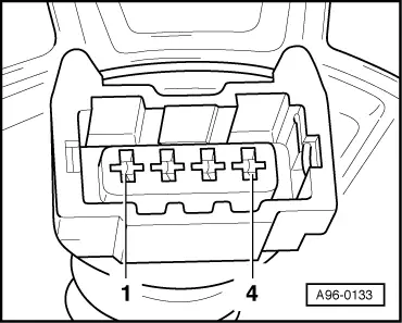
If the fault remains in the same cylinder:

Check the earth connection for the ignition coil

  • ‒ Unplug the connector from the ignition coil.
 
A28-0003
  • ‒ → Check the earth connection from contact 4a on the 3 pin connector to the engine earth for an open circuit or short to positive.
  • ‒ If necessary, rectify open circuit or short circuit.

If the earth connection is OK:

 
A28-0003

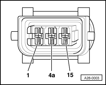
Check the power supply to the ignition coil

  • ‒ → Connect the multimeter for voltage measurement to contact 15 on the connector and the earth.
  • ‒ Switch on the ignition.
  • Specified value: approx battery voltage

If the specified value is not achieved:

  • ‒ Check the wiring.

=> Current Flow Diagrams, Electrical Fault Finding and Fitting Locations binder

If the specified value is achieved:

Checking actuation

  • ‒ Remove the 4-pin connector from the power output stage => Overview of fitting locations - Page 24-5.
  • ‒ Switch on the ignition.
 
A96-0133
  • ‒ → Connect the V.A.G 1527 diode test lamp to the following contacts on the connector:

4-pin connector on the wiring harness contact

Specified value

1 + earth

Diode test lamp should

2 + earth

light up

3 + earth

4 + earth

If the specified values are not achieved:

  • ‒ Switch the ignition off.
 
A28-0003
  • ‒ → Unplug the 3 pin connector on the relevant ignition coil.

  • ‒ Check the wiring between the power output stage and contact 1 on the relevant ignition coil connector for an open circuit.
 
A96-0133

Contact on 4 pin connector for output stage

Contact 1 on 3 pin connector for ignition coil

Connector

Cylinder

1

1

2

3

3

4

4

2

  • ‒ If necessary, rectify open circuit or short circuit.

Checking output stages for ignition coils > < Technical data