audi Workshop Repair Guides

Audi Workshop Service and Repair Manuals

Checking altitude sensor > < Checking the boost pressure control
Motronic fuel injection and ignitionsystem (4-cyl. turbo)
Checking the boost pressure system
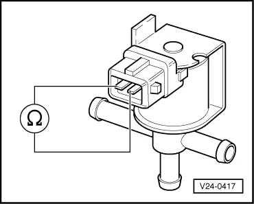
Checking solenoid valve for boost pressure control

Checking operation

  • ‒ Pull the hoses off the -N75 solenoid valve for boost pressure control
    => Fitting locations -Overview - Page 24-5.
  • ‒ Connect auxiliary hose.
  • ‒ Start the final control diagnosis and actuate the -N75 solenoid valve for boost pressure control .
 
→ Display readout:
Final control diagnosis    ⇒
-N75 solenoid valve for boost pressure control
  • The valve should click...
  • ...and should open and close (check by blowing into the auxiliary hose).

If the valve does not click:

  • ‒ Check the solenoid valve for boost pressure control electrically .
  • When there is no electrical signal, the long connection is closed.

If the solenoid valve clicks, but does not open and close properly:

  • ‒ Replace the solenoid valve for boost pressure control (N75).

Electrical check on solenoid valve for boost pressure control (N75).

 
V24-0417
  • ‒ Unplug the connector from the valve
    => Fitting locations - Overview - Page 24-5.
  • ‒ → Connect the V.A.G 1526 hand held multimeter for resistance measurement to the valve.
  • Specified value: 25...35 ω.

If the specified value is not achieved:

  • ‒ Replace the solenoid valve for boost pressure control (N75).

If the specified value is achieved:

  • ‒ Check the power supply from the solenoid valve for boost pressure control => Page 24-38.

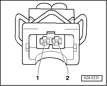
Check the power supply to the solenoid valve for boost pressure control (N75).

 
N24-0231
  • ‒ → Connect the V.A.G 1526 hand held multimeter for voltage measurement to contact 1 of the connector and the earth.
  • ‒ Operate the starter briefly (the engine may start briefly).
  • Specified value: approx. battery voltage.

If the specified value is not achieved:

  • ‒ Check the wiring from contact 1 on the connector via the fuse to the fuel pump relay for an open circuit or short circuit.

=> Current Flow Diagrams, Electrical Fault Finding and Fitting Locations binder

If the specified value is achieved:

  • ‒ Check the actuation for the solenoid valve for boost pressure control => Page 24-39.

Checking the actuation of the solenoid valve for the boost pressure control (N75)

  • ‒ Unplug the connector from the solenoid valve (N75) and connect the V.A.G 1527 diode test lamp between connector contacts 1 and 2.
  • ‒ Start the final control diagnosis and actuate the N75 solenoid valve for boost pressure control .

The diode test lamp should start flashing.

  • ‒ If diode test lamp does not flash or if the lamp is lit continuously. Check the wiring.
  • ‒ Connect the V.A.G 1598/22 test box to the wiring harness for the engine control unit
    .
 
N24-0231

→ The following wiring should be checked for a short to positive or negative and an open circuit:

2-pin connector on the wiring harness contact.

Test box V.A.G 1598/22 contact.

2

64

  • ‒ If necessary, rectify open circuit or short circuit.

Checking altitude sensor > < Checking the boost pressure control