audi Workshop Repair Guides

Audi Workshop Service and Repair Manuals

Wiring and component check with test box V.A.G 1598/22 > < Technical data
Motronic fuel injection and ignitionsystem (4-cyl. turbo)
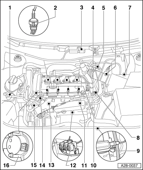
Repairing the Motronic fuel injection system
Overview of fitting locations
 
A28-0037
  • Solenoid valve 1 for activated carbon canister (N80)
  • 4-pin connector
    • ◆ For lambda probe and lambda probe heating
    • ◆ Located on underside of car on right hand side
  • Engine control unit (J220)
  • Ignition coils
    • ◆ Cylinder 1 (N)
    • ◆ Cylinder 2 (N128)
    • ◆ Cylinder 3 (N158)
    • ◆ Cylinder 4 (N163)
  • Solenoid valve for boost pressure control (N75)
 
A28-0037
  • Air mass meter (G70)
  • Output stage for ignition coils (N122)
    • ◆ at the air cleaner

Note:

In certain vehicles, the output stage may be installed in the plenum chamber on the wiper motor.

  • Sensor for coolant temperature (G62)
  • Engine speed sensor (G28)
  • Injectors
    • ◆ Cylinder 1 (N30)
    • ◆ Cylinder 2 (N31)
    • ◆ Cylinder 3 (N32)
    • ◆ Cylinder 4 (N33)
  • Knock sensor 2 (G66)
 
A28-0037
  • 3-pin connector
    from left
    • ◆ For knock sensor 1
    • ◆ For engine speed sensor
    • ◆ For knock sensor 2
  • Knock sensor 1 (G61)
  • Intake air temperature sensor (G42)
  • Throttle valve control unit (J338)
  • Hall sensor (G40)

Wiring and component check with test box V.A.G 1598/22 > < Technical data