audi Workshop Repair Guides

Audi Workshop Service and Repair Manuals

Checking ignition transformer > < Test data, spark plugs
Motronic injection and ignition system (4-cyl.)
Servicing ignition system
Checking Hall sender

Special tools, workshop equipment, testers, measuring instruments and auxiliary items required

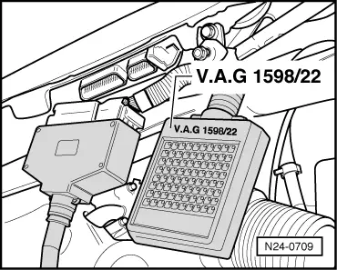
  • ◆ Test box V.A.G 1598/22
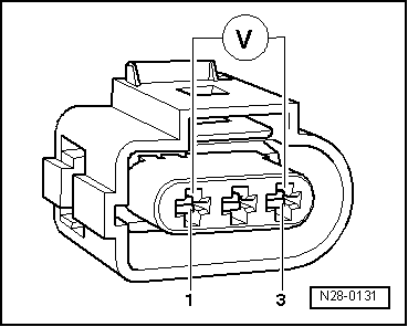
  • ◆ Hand multimeter V.A.G 1526 or multimeter V.A.G 1715
  • ◆ Adapter set V.A.G 1594
  • ◆ Current flow diagram

Check conditions

  • ● The battery voltage must be at least 11.5 V.
  • ● If the vehicle is equipped with an air conditioning system, this must be switched off.
  • ● All electrical consumers, e.g. lights and rear window heating must be switched off.
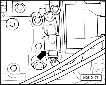
  • ● Hall sender screwed on tight
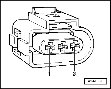
Test sequence

 
N28-0176
  • ‒ → Pull 3-pin connector off Hall sender -arrow-.

 
N28-0131
  • ‒ → Connect multimeter to measure voltage with adapter cables from V.A.G 1594 to contacts 1 (positive) and 3 (earth) on the Hall sender connector.
  • ‒ Switch on ignition.
        Specification: min. 4.5 V
  • ‒ Switch off ignition.
 
N24-0709

If no voltage is present:

  • ‒ → Connect test box V.A.G 1598/22 to control unit wiring harness
    .

 
A24-0096
  • ‒ → Check wiring between test box and 3-pin connector (connector to control unit) for open circuit using current flow diagram.
        Contact 1+socket 62
        Contact 2+socket 60
        Contact 3+socket 54
        Wire resistance: max. 1.5 ω
  • ‒ Additionally check wires for short to one another, to vehicle earth and to battery positive.
        Specification: ∞ω

If no wiring fault is detected and voltage was present between contacts 1+3:

  • ‒ Renew Hall sender (G40)
    => Page 28-5, item 8.

If no wiring fault is detected and no voltage was present between contacts 1+3:

  • ‒ Replace engine control unit
    => Page 24-134.

Checking ignition transformer > < Test data, spark plugs