audi Workshop Repair Guides

Audi Workshop Service and Repair Manuals

Checking ignition system > < Testing knock sensors
Motronic Injection and Ignition System (4-cyl.)
Testing ignition system
Checking Hall sender

Fitting location of Hall sender => Page .

Notes:

  • ◆ Under normal operating conditions the signal from the Hall sender tells the engine control unit the ignition position for cylinder 1.
  • ◆ If no Hall sender signal is received, the knock sensor signals can no longer be assigned to the cylinders. If this happens, the knock control system is deactivated and the ignition timing is slightly retarded in order to prevent knocking.
  • ◆ Even if no Hall sender signal is received, the engine will continue to run and can also be re-started. The reason for this is as follows:
    • ‒ The fact that the injection system is one revolution out of phase does not have any noticeable effect. If this happens, the fuel is injected upstream of the closed inlet valve instead of while the inlet valve is open. This has only a minor influence on the quality of the air/fuel mixture.
    • ‒ With the twin-spark ignition system an ignition spark is produced for each cylinder after every engine revolution, and not after alternate revolutions as is normally the case.
 
V96-0836
  • ‒ → Connect diode test lamp V.A.G 1527 to contacts 1 and 2 of the Hall sender connector from behind (without unplugging the connector from the Hall sender).

Note:

The connector contacts are numbered on the back of the connector.

  • ‒ Operate starter for a few seconds.
  • ‒ The diode test lamp should flash briefly after every second revolution of the engine.
  • ‒ Unplug connector from Hall sender.
  • ‒ Switch ignition on.
  • ‒ Connect hand-held multimeter V.A.G 1526 to contacts 1 (positive) and 3 (earth) of the Hall sender connector.

Specification: 4.5 ... 5.5 V

  • ‒ Connect hand-held multimeter V.A.G 1526 to contacts 2 and 3 of the Hall sender connector.

Specification: approx. battery voltage

  • ‒ If the voltage readings match the specifications but the diode test lamp does not flash, fit a new Hall sender.
 
V96-0836
  • ‒ If the voltage readings do not match the specifications, test the wiring as follows:
  • ‒ Connect test box V.A.G 1598/22 to the wiring harness for the engine control unit.
  • ‒ → Test the wiring from the Hall sender...
 
A28-0022
  • ‒ → ... to the engine control unit for open circuits and short circuits to positive or earth.

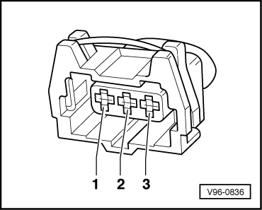
Contact on 3-pin connector for Hall sender

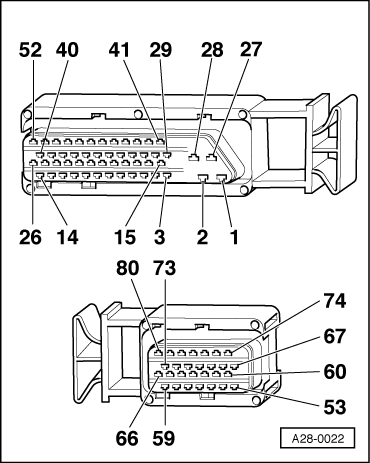
Contact on control unit connector

1 (positive)

62

2 (signal)

76

3 (earth)

67

  • ‒ If all the test results so far have been OK but a fault related to the camshaft sensor (Hall sender) is displayed again after erasing the fault memory as a test measure, the cause may be as follows:
    • ‒ Rotor aperture for Hall sender misaligned
  • ‒ Unbolt Hall sender, then check to ensure that the rotor ring is correctly aligned on the camshaft. If incorrectly installed, the catch will be pressed flat when the securing screw is tightened.
  • ‒ If the rotor ring is correctly aligned, check the position of the camshaft in relation to the crankshaft.

=> 4-Cylinder Engine, Mechanics; Repair Group 15; Cylinder head, valve gear; Removing and installing camshafts and camshaft adjustment

Note on signal testing with an oscilloscope:

The centre point of the window of the Hall sender must lie on the third downwards side of the engine speed signal after the reference mark gap.

Checking ignition system > < Testing knock sensors