audi Workshop Repair Guides

Audi Workshop Service and Repair Manuals

Checking engine speed sender > < Checking intake air temperature sender
Motronic injection and ignition system (4-cyl.)
Checking components
Checking coolant temperature sender

Special tools, workshop equipment, testers, measuring instruments and auxiliary items required

  • ◆ Fault reader V.A.G 1551 (or vehicle system tester V.A.G 1552) with cable V.A.G 1551/3
  • ◆ Test box V.A.G 1598/22
  • ◆ Hand multimeter V.A.G 1526 or multimeter V.A.G 1715
  • ◆ Adapter set V.A.G 1594
  • ◆ Current flow diagram

Test conditions

  • ● Engine must be cold.

Test sequence

  • ‒ Connect the fault reader V.A.G 1551 (V.A.G 1552). Then switch ignition on and select engine control unit with the "Address word" 01.
    (Connecting fault reader and selecting engine control unit .)
 
→ Indicated on display:
Rapid data transfer    HELP
Select function XXX
  • ‒ Press keys 0 and 8 for the function "Read measured value block" and confirm entry with Q key.
 
→ Indicated on display:
Read measured value block
Input display group number XXX
  • ‒ Press keys 0, 0 and 4 for "Display group number 4" and confirm entry with Q key.
 
→ Indicated on display:
(1...4 = Display zones)
Read measured value block 4    ⇒
    1    2    3    4
  • ‒ Read off coolant temperature value in display zone 3.
  • ‒ Perform check according to following table:

Display

Cause

Continuation of check

Approx. coolant temperature1)

---

Only if spora-
dic faults
have been
detected:2)
=> Page 24-56

-40 °C

Open circuit or short to positive

=> Page 24-58

129 °C

Short to earth

=> Page 24-60

    1)    If a temperature is displayed which deviates greatly from the ambient temperature of the sender, check sender wiring for transfer resistances.

    2)    Check is only possible when the engine is cold.

Continuation of check when display = coolant temperature:

Functional check of sender

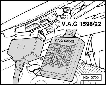
  • ‒ Connect fault reader V.A.G 1551 (V.A.G 1552). Start engine and select "Address word" 01 of engine control unit. When doing this the engine must be running at idling speed.
    (Connecting fault reader and selecting engine control unit => Page 01-7.)
 
→ Indicated on display:
Rapid data transfer    HELP
Select function XXX
  • ‒ Press keys 0 and 8 for the function "Read measured value block" and confirm entry with Q key.
 
→ Indicated on display:
Read measured value block
Input display group number XXX
  • ‒ Press keys 0, 0 and 4 for "Display group number 4" and confirm entry with Q key.
 
→ Indicated on display:
(1...4 = Display zones)
Read measured value block 4    ⇒
    1    2    3    4
  • ‒ Observe coolant temperature value in display zone 3 with engine running. The temperature value must
        increase evenly without interruption.

Notes:

  • ◆ Temperature increases in steps of 1.0 °C.
  • ◆ If irregular engine running occurs in certain temperature ranges and the temperature figure does not increase without interruption, the temperature signal is temporarily interrupted and the sender must be renewed.
  • ‒ Press ⇒key.
  • ‒ Press keys 0 and 6 for the function "End output" and confirm entry with the Q key.
  • ‒ Switch off ignition.

If the specification is not obtained:

  • ‒ Replace coolant temperature sender (G62) with coolant temperature gauge sender (G2) , item 28.
 
R24-0012

Continuation of check when display shows -40 °C:

  • ‒ → Pull the 4 pin connector off coolant temperature sender (G62) with coolant temperature gauge sender (G2) -arrow-.

 
N24-1040
  • ‒ → Bridge connector contacts 1+3 using aux. cables from V.A.G 1594 and observe display.

Display jumps to 129 °C:

  • ‒ Press ⇒key.
  • ‒ Press keys 0 and 6 for the function "End output" and confirm entry with the Q key.
  • ‒ Switch off ignition.
  • ‒ Replace coolant temperature sender (G62) with coolant temperature gauge sender (G2) , item 28.

If the display remains at -40 °C:

  • ‒ Press ⇒key.
  • ‒ Press keys 0 and 6 for the function "End output" and confirm entry with the Q key.
  • ‒ Switch off ignition.
 
N24-0709
  • ‒ → Connect test box V.A.G 1598/22 to control unit wiring harness
    => Page 24-121.
 
N24-1040
  • ‒ → Check wires between test box and 4-pin connector (connector to control unit) for open circuit using current flow diagram.
        Contact 1+socket 54
        Contact 3+socket 74
        Wire resistance: max. 1.5 ω
  • ‒ Additionally check wires for short to one another, to vehicle earth and to battery positive.
        Specification: ∞ω

If no fault is detected in the wiring:

  • ‒ Replace coolant temperature sender (G62) with coolant temperature gauge sender (G2) , item 28.

Continuation of check when display shows 129 °C:

 
R24-0012
  • ‒ → Pull the 4 pin connector off coolant temperature sender (G62) with coolant temperature gauge sender (G2) -arrow-.

If the display jumps to -40 °C:

  • ‒ Press ⇒key.
  • ‒ Press keys 0 and 6 for the function "End output" and confirm entry with the Q key.
  • ‒ Switch off ignition.
  • ‒ Replace coolant temperature sender (G62) with coolant temperature gauge sender (G2) , item 28.

If display remains at 129 °C:

  • ‒ Press ⇒key.
  • ‒ Press keys 0 and 6 for the function "End output" and confirm entry with the Q key.
  • ‒ Switch off ignition.
 
N24-0709
  • ‒ → Connect test box V.A.G 1598/22 to control unit wiring harness
    => Page 24-121.
 
N24-1040
  • ‒ → Check wires between test box and 4-pin connector (connector to control unit) for open circuit using current flow diagram.
        Contact 1+socket 54
        Contact 3+socket 74
        Wire resistance: max. 1.5 ω
  • ‒ Additionally check wires for short to one another, to vehicle earth and to battery positive.
        Specification: ∞ω

If no fault is detected in the wiring:

  • ‒ Replace coolant temperature sender (G62) with coolant temperature gauge sender (G2) , item 28.

Checking engine speed sender > < Checking intake air temperature sender