audi Workshop Repair Guides

Audi Workshop Service and Repair Manuals

Checking engine operating mode > < Idling check
Motronic injection and ignition system (4-cyl.)
Checking functions
Checking Lambda probe and Lambda regulation before catalyst

Special tools, workshop equipment, testers, measuring instruments and auxiliary items required

  • ◆ Fault reader V.A.G 1551 (or vehicle system tester V.A.G 1552) with cable V.A.G 1551/3
  • ◆ Test box V.A.G 1598/22
  • ◆ Hand multimeter V.A.G 1526 or multimeter V.A.G 1715
  • ◆ Adapter set V.A.G 1594
  • ◆ Current flow diagram

Check conditions

  • ● The fuses must be OK.
  • ● The battery voltage must be at least 11.5 V.
  • ● Exhaust system between catalyst and cylinder head must be free of leaks
  • ● Coolant temperature must be at least 80 °C, =>display group 04, display zone 3.

Functional check

  • ‒ Connect fault reader V.A.G 1551 (V.A.G 1552). Start engine and select "Address word" 01 of engine control unit. When doing this the engine must be running at idling speed.
    (Connecting fault reader and selecting engine control unit .)
 
→ Indicated on display:
Rapid data transfer    HELP
Select function XXX
  • ‒ Press keys 0 and 8 for the function "Read measured value block" and confirm entry with Q key.
 
→ Indicated on display:
Read measured value block
Input display group number XXX
  • ‒ Press keys 0, 3 and 0 for the "Display group number 30" and confirm entry with Q key.
 
→ Indicated on display:
(1...2 = Display zones)
Read measured value block 30    ⇒
    1    2
  • ‒ Check Lambda control status before catalyst (display zone 1):
        Specification: 1 1 1
    (Significance => Page 01-79)

Notes:

  • ◆ The first position of the 3 digit number block fluctuates between 0 and 1 (Lambda probe heating on and off).
  • ◆ Depending upon the status of the Lambda control the 3 digit number block can show 0 or 1.
  • ◆ The bits in display zone 1 will not be set to 1 until the catalyst temperature has exceeded 400.0 °C (=> display group 34, display zone 2).

If the specification is not obtained:

  • ‒ Check the Lambda probe heating before catalyst
    => Page 24-29.

If the specification is obtained:

  • ‒ Change to display group 32 as follows:
  • ‒ Press C key.
  • ‒ Press keys 0, 3 and 2 for "Display group number 32" and confirm entry with Q key.
 
→ Indicated on display:
(1...2 = Display zones)
Read measured value block    32    ⇒
    1    2
  • ‒ Check Lambda learnt values at idling speed (additive) in display zone 1.
        Specification: -10.0...10.0 %
  • ‒ Check Lambda learnt values at part load (multiplicative) in display zone 2.
        Specification: -10.0...10.0 %

If the specifications are not obtained:

  • ‒ , Evaluating display group 32

If the specifications are obtained:

  • ‒ Change to display group 33 as follows:
        V.A.G 1551: Press key 3
        V.A.G 1552: Press key ↑
 
→ Indicated on display:
(1...2 = Display zones)
Read measured value block    33    ⇒
    1    2
  • ‒ Observe Lambda regulation in display zone 1. The display must fluctuate at least 2 % in the range
        -10.0...10.0 %
  • ‒ Press ⇒key.
  • ‒ Press keys 0 and 6 for the function "End output" and confirm entry with the Q key.
  • ‒ Switch off ignition.

If the Lambda regulation does not fluctuate in display zone 1:

  • ‒ Carry out a test drive to remove possible residue on Lambda probe and repeat check.

Observe the valid safety precautions when carrying out a road test => Page 24-24.

  • ‒ Check Lambda probe wiring for Lambda probe 1 => Page 24-101.

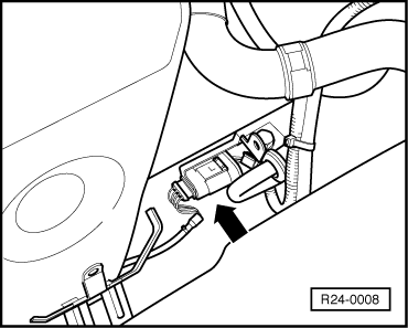
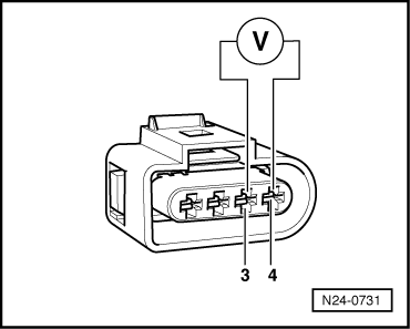
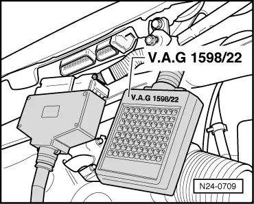
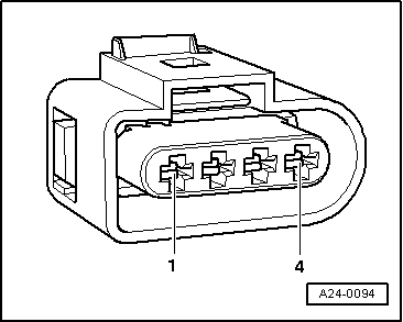
Check Lambda probe wiring Lambda probe 1

 
R24-0008
  • ‒ → Separate the 4-pin connector (black) to Lambda probe before catalyst (G39) -arrow-.
 
N24-0731
  • ‒ → Connect multimeter with aux. cables from V.A.G 1594 to measure voltage at contacts 3+4 (connector to engine control unit).
  • ‒ Switch on ignition and measure basic voltage.
        Specification: 0.40...0.50 V
  • ‒ Switch off ignition.

If the specification is obtained:

  • ‒ Renew Lambda probe before catalyst (G39)
    , item 13.

If the specification is not obtained:

 
N24-0709
  • ‒ → Connect test box V.A.G 1598/22 to control unit wiring harness
    => Page 24-121.
 
A24-0094
  • ‒ → Check wiring between test box and 4 pin connector (to control unit) for open circuit according to current flow diagram.
        Contact 3+socket 21
        Contact 4+socket 47
        Wire resistance: max. 1.5 ω
  • ‒ Check wiring at connector contacts 3+4 for short circuit to contacts 1+2 according to current flow diagram.
        Specification: ∞ω

If no fault is detected in the wiring:

  • ‒ Renew Lambda probe before catalyst (G39)
    , item 13.

Checking engine operating mode > < Idling check