audi Workshop Repair Guides

Audi Workshop Service and Repair Manuals

Testing auxiliary signals > < Testing idling speed switch
Motronic Injection and Ignition System (4-cyl.)
Testing throttle valve control part
Testing throttle valve positioner sender and throttle valve potentiometer

Testing sender voltage readings

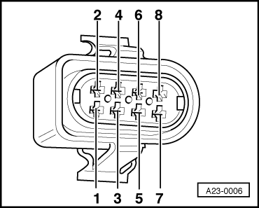
  • ‒ Disconnect the 8-pin plug on the throttle valve control part.
 
A23-0006
  • ‒ Switch on ignition.
  • ‒ → Measure voltage between contacts 4 and 7 on the 8-pin plug using hand-held multimeter V.A.G 1526.

Specification: at least 4.8 V

If the value is as specified, reconnect the 8-pin plug.

  • ‒ Start the engine.
  • ‒ Read measure value block (function 08) and select Display Group 98 .
 
→ Indicated on display:
Read measured value block    98    ⇒
4.420 V    3.080 V    Idling    ................

The values in display zones 1 and 2 should be between 0.5 and 4.9 V.

  • ‒ If the values are not as specified, switch off the ignition.
  • ‒ Connect test box V.A.G 1598/22 to the wiring harness for the engine control unit
    => Page 24-10.
 
A23-0006
  • ‒ Disconnect the 8-pin plug on the throttle valve control part.
  • ‒ → Test for open circuit between the test box and the 8-pin plug using multimeter V.A.G 1526.

Contact on
8-pin plug

Contact on
test box

1

66

2

59

3

69

4

62

5

75

7

67

8

74

  • ‒ Use the multimeter to test the wires for short circuits with each other.
  • ‒ Rectify any open circuits and remove any dirt from the contacts. Erase fault memory and perform basic setting of throttle valve control part => Page 24-54.
  • ‒ If the value is still not as specified, check the throttle valve for dirt and stiffness. Clean if necessary.
  • ‒ Repeat basic setting of throttle valve control part => Page 24-54.
  • ‒ If it is not possible to start the basic setting or if the procedure cannot be successfully completed, fit a new throttle valve control part.
  • ‒ Perform basic setting of throttle valve control part => Page 24-54.
  • ‒ If it is not possible to start the basic setting or if the procedure cannot be successfully completed, fit a new engine control unit
    => Page 24-10.

Testing auxiliary signals > < Testing idling speed switch