audi Workshop Repair Guides

Audi Workshop Service and Repair Manuals

Checking air mass meter > < Checking injectors
Motronic Injection and Ignition System (4-cyl.) 08.97ä
Servicing Motronic injection system
Testing fuel pump relay and activation
 
A24-0100

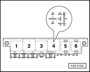
Note:

→ The fuel pump relay is located in the central electrics in the left-hand footwell, relay position 4.

Special tools, testers and auxiliary items

  • ◆ Hand multimeter V.A.G 1526 or V.A.G 1526 A
  • ◆ Diode test lamp V.A.G 1527
  • ◆ Adapter set V.A.G 1594
  • ◆ Test box V.A.G 1598/22

A - Testing fuel pump relay -J17

 
A97-0022
  • ‒ Remove storage bin in front left-hand footwell.
  • ‒ → Remove fuse 28 from fuse holder and connect diode test lamp V.A.G 1527 between earth and one of the two contacts for fuse 28.
  • ‒ Operate the starter briefly.

The fuel pump relay should pick up (can be felt and heard) and the diode test lamp should light up.

  • ‒ If the fuel pump relay picks up but the diode test lamp does not light up, repeat the test on the other contact.
 
A24-0100
  • ‒ → If the diode test lamp still does not light up, test for open circuits in the wiring between fuse 28 and contact 23 in relay position 4.

=> Current flow diagrams, Electrical fault finding and Fitting locations binder

  • ‒ If no open circuit is detected, fit a new fuel pump relay.
  • ‒ If the fuel pump relay does not pick up, test activation
    .
  • ‒ If the power supply and activation are OK, fit a new fuel pump relay.

B - Testing power supply and activation of fuel pump relay

  • ‒ Remove fuel pump relay -J17 from central electrics, relay position 4.

Testing power supply

  • ‒ Switch ignition on.
 
A24-0100
  • ‒ → Connect hand-held multimeter V.A.G 1526 first to contact 19 (positive) and earth on relay panel, then to contact 17 (positive) and earth on relay panel.

Specification: approx. battery voltage in each case

  • ‒ If the values are not as specified, rectify the open circuit.

=> Current flow diagrams, Electrical fault finding and Fitting locations binder

 
A24-0100

Testing activation

  • ‒ → Connect diode test lamp V.A.G 1527 to contact 16 (earth) and positive.
  • ‒ The diode test lamp should light up and remain lit when the starter is operated.

Note:

Diode test lamps with a low current draw do not go out completely but continue to glow faintly until the starter is operated.

 
A28-0022

If the diode test lamp does not light up, test the wiring as follows:

  • ‒ → Connect test box V.A.G 1598/22 to wiring harness for engine control unit.
    .
  • ‒ Connect hand-held multimeter between contact 16 on relay panel and socket 4 on the test box, then test wiring for open circuits.
  • ‒ Rectify any open circuits.

=> Current flow diagrams, Electrical fault finding and Fitting locations binder

  • ‒ If there is no open circuit and the diode test lamp does not light up, fit a new engine control unit => Page 24-10.
  • ‒ If both the fuel pump relay activation and the wiring are OK, fit a new fuel pump relay.
  • ‒ Refit fuse 28.

Checking air mass meter > < Checking injectors