audi Workshop Repair Guides

Audi Workshop Service and Repair Manuals

Testing intake air temperature sender -G42 > < Technical data
Motronic injection and ignition system (4-cyl. turbo)
Testing ignition system
Testing ignition coils with output stages
 
G24-0022

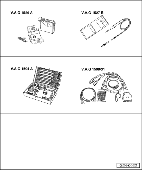
Special tools and workshop equipment required

  • ◆ V.A.G 1526 A
  • ◆ V.A.G 1527 B
  • ◆ V.A.G 1594 A
  • ◆ V.A.G 1598/31

Note:

Each ignition coil is combined with its output stage as a single component.

 
A10-0515
  • ‒ → Remove engine cover panel -arrows-.

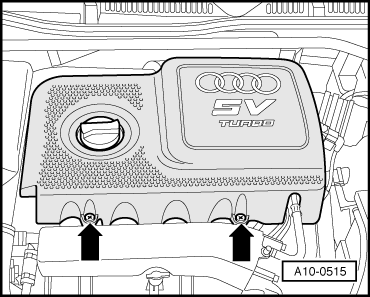
The procedure for identifying an inoperative or misfiring cylinder is as follows:

  • ‒ Unplug the connectors from the injectors in turn with the engine running, and observe how the engine runs.
  • or
  • ‒ Compare the spark plugs of all cylinders with each other and check for soot on the electrodes.

When the defective cylinder has been identified:

  • ‒ Swap spark plug of defective cylinder with one from another cylinder.

If the fault moves with the spark plug:

  • ‒ Renew spark plug.

If the fault remains in the same cylinder:

  • ‒ Swap ignition coil of defective cylinder with one from another cylinder.

If the fault moves with the ignition coil:

  • ‒ Renew ignition coil.

If the fault remains in the same cylinder:

Testing earth connections

  • ‒ Unplug 4-pin connector from ignition coil.
 
A24-0094
  • ‒ → Connect voltage tester V.A.G 1527 B as follows:

Connector
Contact

Measure against

2

Battery positive

4

Battery positive

    • ‒ The LED should light up.

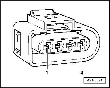
If the LED does not light up:

  • ‒ Check the wiring.

=> Current flow diagrams, Electrical fault finding and Fitting locations

If the LED lights up:

Checking voltage supply

 
A24-0094
  • ‒ → Connect multimeter (voltage measurement range) as follows:

Connector
Contact

Measure against

1

Engine earth

  • ‒ Switch on ignition.
    • ‒ Specification: approx. battery voltage

If the specification is not obtained:

  • ‒ Check the wiring.

=> Current flow diagrams, Electrical fault finding and Fitting locations

If the specification is still not attained:

  • ‒ Test activation of output stage .

Testing activation of output stages

  • ‒ Unplug the connectors from all four injectors.

Note:

It is important to ensure that no fuel is injected during the test as this would damage the catalytic converter. The connectors on the injectors must therefore be unplugged.

  • ‒ Unplug 4-pin connector from ignition coil.
 
A24-0094
  • ‒ → Connect voltage tester V.A.G 1527 B to contacts 2 and 3 of the connector.
  • ‒ Operate starter briefly.
    • ‒ The LED should flash briefly.

If the specifications are not obtained:

  • ‒ Connect test box V.A.G 1598/31 to wiring harness for engine control unit. Do not connect to the engine control unit itself.
    => Page 24-16.
 
A24-0094
  • ‒ → Test for open circuit and short to positive or earth in the following wiring connections:

Connector
Contact

Test box V.A.G 1598/31
Socket

3 (cylinder 1)

102

3 (cylinder 2)

95

3 (cylinder 3)

103

3 (cylinder 4)

94

  • ‒ Rectify any open/short circuit as necessary.

If no wiring fault is detected:

  • ‒ Renew ignition coil with output stage (combined as a single component).

Testing intake air temperature sender -G42 > < Technical data