
A3 Mk1
|
Checking electronic engine power control (electronic throttle)
Checking brake light switch and brake pedal switch
|
 |
|
|
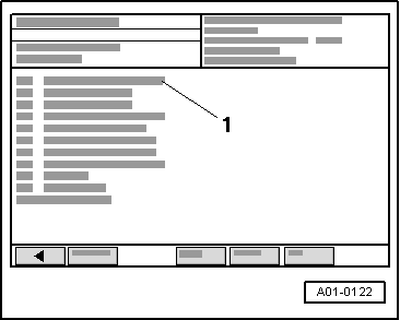
→ Display on VAS 5051:
|
 |
|
|
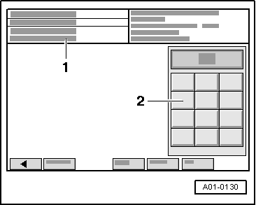
→ Display on VAS 5051:
|
 |
||||||||||||||||||||||||||||||||||||||||||||||
|
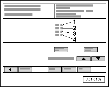
→ Display on VAS 5051:
If the display is not as described: Check switch
| ||||||||||||||||||||||||||||||||||||||||||||||
 |
|
If the specified values are not obtained:
If specifications are attained:
Checking power supply |
 |
|||||||||
If the LED does not illuminate:
=> Current Flow Diagrams, Electrical Fault-finding and Fitting Locations binder
If the LED illuminates:
Checking actuation
|
|
|||||||
|