audi Workshop Repair Guides

Audi Workshop Service and Repair Manuals

Testing power steering pressure switch -F88 > < Testing brake light switch and brake pedal switch
Motronic injection and ignition system (4-cyl. turbo)
Testing auxiliary signals
Testing clutch pedal switch -F36
 
G24-0023

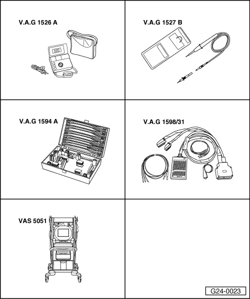
Special tools and workshop equipment required

  • ◆ V.A.G 1526 A
  • ◆ V.A.G 1527 B
  • ◆ V.A.G 1594 A
  • ◆ V.A.G 1598/31
  • ◆ VAS 5051 with VAS 5051/1
  • or
  • ◆ V.A.G 1551 with V.A.G 1551/3 A

Note:

This signal is used to avoid over-revving and load change jolts when disengaging the clutch. It is also needed for the cruise control system.

Test sequence

  • ‒ Connect vehicle diagnostic, testing and information system VAS 5051 (or fault reader V.A.G 1551) and select engine electronics control unit by entering address word "01" ( .)
    When doing this the ignition must be switched on.
 
→ Indicated on display:
Rapid data transfer     HELP
Select function XX
  • ‒ Enter "08" to select the function "Read measured value block" and confirm entry with Q key.
 
→ Indicated on display:
Read measured value block    Q
Enter display group number XXX
  • ‒ Enter "066" for Display Group 066 and confirm entry with Q key.
 
→ Indicated on display:
Read measured value block 66    ⇒
    1    2    3    4
  • ‒ Check display value for clutch pedal switch (display zone 2).

Display zones

1

2

3

4

Display Group 066: Signals to engine control unit

Display

xxx km/h

XXXX

xxx km/h

XXXX

Indicates

Actual road speed

Switch positions

Specified road speed

Switch positions

Range


X0XX
X1XX

Specification

X0XX
(clutch pedal
not depressed)

X1XX
(clutch pedal
depressed)

Note

X = irrelevant

If the display values do not appear as described:

Testing switch

  • ‒ Remove storage compartment on driver's side.

=> General body repairs, Interior; Repair group 68; Storage compartments, covers and trim parts; Removing and installing driver's storage compartment

  • ‒ Unplug connector from clutch pedal switch.
 
A24-0208
  • ‒ → Connect multimeter (resistance measurement range) between contacts 1 and 2.
    • ‒ Specification: approx. 0 ω
  • ‒ Depress the clutch pedal.
    • ‒ Specification: ∞ ω (no continuity)

If the specification is not attained:

  • ‒ Renew clutch pedal switch.

If the specification is attained:

Testing voltage supply

 
A24-0201
  • ‒ → Connect voltage tester V.A.G 1527 B as follows:

Connector
Contact

Measure against

1

Body earth

  • ‒ Switch on ignition.
    • ‒ The LED should light up.

If the LED does not light up:

  • ‒ Test for open circuit or short to earth in wiring between fuel pump relay and contact 1 on connector via fuse.

=> Current flow diagrams, Electrical fault finding and Fitting locations

If the LED lights up:

Checking activation

  • ‒ Connect test box V.A.G 1598/31 to wiring harness for engine control unit. Do not connect to the engine control unit itself.
    => Page 24-16.
 
A24-0201
  • ‒ → Test for open circuit and short to positive or earth in the following wiring connections:

Connector
Contact

Test box V.A.G 1598/31
Socket

2

39

  • ‒ Rectify short circuit or open circuit if necessary.

Testing power steering pressure switch -F88 > < Testing brake light switch and brake pedal switch