audi Workshop Repair Guides

Audi Workshop Service and Repair Manuals

Testing air conditioner compressor shut-off > < Testing fuel consumption signal for on-board computer
Motronic injection and ignition system (4-cyl. turbo)
Testing auxiliary signals
Testing road speed signal
 
G24-0023

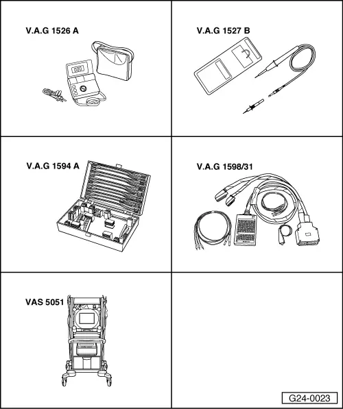
Special tools and workshop equipment required

  • ◆ V.A.G 1526 A
  • ◆ V.A.G 1527 B
  • ◆ V.A.G 1594 A
  • ◆ V.A.G 1598/31
  • ◆ VAS 5051 with VAS 5051/1
  • or
  • ◆ V.A.G 1551 with V.A.G 1551/3 A

Notes:

  • ◆ The road speed signal is generated by the road speed sender -G68 (on the gearbox) and is processed in the dash panel insert.
  • ◆ The processed signal goes to contact 54 on the engine control unit and is used for idling speed stabilisation and for the damping of load change jolts when changing gear.

Test requirement:

  • ● Speedometer (including display) must be functioning properly.
    Fault-finding:

=> Electrical system; Repair group 90; Dash panel insert; Testing road speed signal

Test sequence

  • ‒ Connect vehicle diagnostic, testing and information system VAS 5051 (or fault reader V.A.G 1551) and select engine electronics control unit by entering address word "01" ( .)
    When doing this the engine must be idling.
Warning:
To avoid accident risks when road testing the vehicle with test equipment, always observe the relevant safety precautions =>
 
→ Indicated on display:
Rapid data transfer     HELP
Select function XX
  • ‒ Enter "08" to select the function "Read measured value block" and confirm entry with Q key.
 
→ Indicated on display:
Read measured value block    Q
Enter display group number XXX
  • ‒ Enter "005" for Display Group 005 and confirm entry with Q key.
 
→ Indicated on display:
Read measured value block 5    ⇒
    1    2    3    4
  • ‒ Take vehicle for a test drive and check whether the road speed appears in display zone 3.
  • ‒ If the road speed does not appear, raise the vehicle (preferably using a lifting platform) until the front left wheel is clear of the ground.
  • ‒ Connect test box V.A.G 1598/31 to wiring harness for engine control unit. Do not connect to the engine control unit itself.
    => Page 24-16.
  • ‒ Connect voltage tester V.A.G 1527 B to sockets 3 (positive) and 54 (road speed signal) on test box V.A.G 1598/31.
  • ‒ Switch on the ignition and turn the front left wheel by hand.
    • ‒ The LED should flash very briefly.

If the LED does not flash:

  • ‒ Test for open circuit and short to positive or earth in the following wiring connection:

Test box
V.A.G 1598/31
Socket

Dash panel insert

Contact

54

=> Current flow diagrams,
=> Electrical fault-finding
=> and Fitting locations binder

  • ‒ Rectify short circuit or open circuit if necessary.

Testing air conditioner compressor shut-off > < Testing fuel consumption signal for on-board computer