audi Workshop Repair Guides

Audi Workshop Service and Repair Manuals

Checking fuel tank breather > < Testing accelerator position senders
Motronic injection and ignition system (4-cyl. turbo)
Vacuum system layout
 
A21-0097

Schematic diagram

  • From fuel tank
  • Activated charcoal filter
    • ◆ With ACF solenoid valve 1 -N80
  • Non-return valve for ACF
    • ◆ Between activated charcoal filter and intake pipe upstream of turbocharger
    • ◆ Installation position (light side/ dark side) as shown in illustration. Arrow indicates direction of flow
  • Turbocharger
  • Vacuum/pressure unit for charge pressure control
 
A21-0097
  • Mechanical air recirculation valve
  • Brake servo
  • Non-return valve
    • ◆ Between brake servo and intake manifold
    • ◆ Installation position (light side/ dark side) as shown in illustration. Arrow indicates direction of flow
  • Solenoid valve for charge pressure control -N75
  • Air mass meter -G70
  • Air cleaner
  • Crankcase breather pressure regulating valve
  • Combination valve for secondary air system
 
A21-0097
  • Vacuum reservoir
    • ◆ Bolted to cylinder head cover
  • Charge air cooler
    • ◆ With charge pressure sender -G31
  • Fuel pressure regulator
  • Throttle valve control part -J338
  • Intake manifold
    • ◆ With intake air temperature sender sender -G42
  • Crankcase breather
  • Non-return valve
    • ◆ Installation position (light side/ dark side) as shown in illustration. Arrow indicates direction of flow
 
A21-0097
  • Air recirculation valve for
    turbocharger -N249
    • ◆ Fitting location
      => Fig.24-143
  • Secondary air inlet valve
    -N112
    • ◆ Fitting location: below bracket on intake manifold
  • Secondary air pump motor -V101
  • Non-return valve
    • ◆ Between activated charcoal filter and intake manifold
    • ◆ Installation position (light side/ dark side) as shown in illustration. Arrow indicates direction of flow
  • Charge air cooler
 
A24-0260

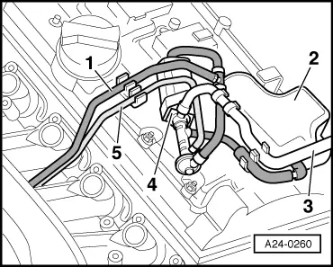
→ Fig.1    Fitting location of air recirculation valve for turbocharger -N249

  • ◆ Fitting location: on cylinder head cover
  •     1 -    To secondary air inlet valve -N112
  •     2 -    Vacuum reservoir
  •     3 -    To mechanical air recirculation valve
  •     4 -    Air recirculation valve for turbocharger -N249
  •     5 -    To connection on intake manifold

Checking fuel tank breather > < Testing accelerator position senders