
A3 Mk1

 Note
Note
|
| Display zones | ||||
| 1 | 2 | 3 | 4 | |
| Display Group 004: Coolant temperature with engine idling | ||||
| Display | xxxx rpm | xx.x V | xxx.x °C | xxx.x °C |
| Display | Engine speed | Battery voltage | Coolant temperature | Intake air temperature |
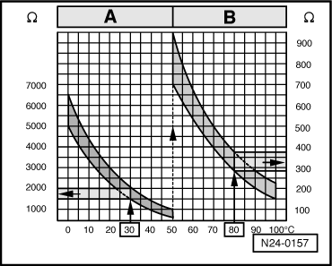
| Operating range | -48.0...143.0 °C | |||
| Specification | xxxx rpm | 12.0...15.0 V | Temperature value must increase steadily | From ambient temperature to 110 °C |
|
|
|
|
|
|
|
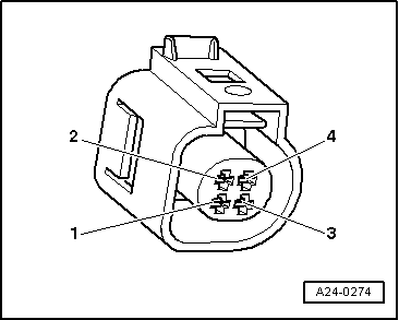
| Connector Contact | Test box -V.A.G 1598/31- Socket |
| 3 | 108 |
| 4 (signal) | 93 |
|