
A3 Mk1

 Note
Note
|
|
|
|
|
|
|
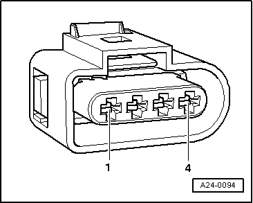
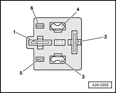
| Connector Contact | Measure to |
| 2 | Battery positive |
| 4 | Battery positive |
Note
|
|
|
| Connector Contact | Measure to |
| 1 | Engine earth |
|
|
|
Note
|
|
|
|
|
|
|
|
| Connector Contact | Test box -V.A.G 1598/31- Socket |
| 3 (cyl. 1) | 102 |
| 3 (cyl. 2) | 95 |
| 3 (cyl. 3) | 103 |
| 3 (cyl. 4) | 94 |
|