audi Workshop Repair Guides

Audi Workshop Service and Repair Manuals

Checking Hall sender G40 > < Checking knock control limit
Checking knock sensors
Special tools and workshop equipment required
t  Portable multimeter -V.A.G 1526C-
t  Adapter set -V.A.G 1594C-
t  121-pin adapter cable -V.A.G 1598/31-
Fitting location ⇒ Overview of fitting locations → Chapter
   

Checking wiring of knock sensors
  Note
t  Electrical checking of knock sensor 1 -G61- and knock sensor 2 -G66- (i.e. the actual sensors) is not possible.
t  Always use gold-plated contacts when repairing the knock sensor connectors.
t  Exact compliance with the tightening torque of 20 Nm is crucial to proper operation of the knock sensors.
t  Check for corrosion of the connector from the knock sensor to the wiring harness.
   
–  Unplug the connector of knock sensor 1 -G61--1-/knock sensor 2 -G66--2- in the engine compartment.
  A28-0048
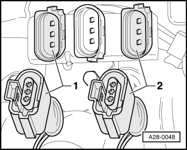
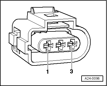
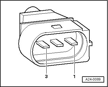
–  Check all three contacts at the knock sensor connector for mutual short circuit (contacts 1+2, 1+3, 2+3).
t  Specification: ∞ Ω (no continuity) - there must be no connection between any of the contacts.
–  If there is, replace the knock sensor.
–  If no short circuit is found, check the wiring of the knock sensors.
Checking wiring between knock sensors and engine control unit
–  Connect the test box -V.A.G 1598/31- to the wiring harness to the engine control unit, but do not connect the actual engine control unit → Chapter.
–  Check for open circuit and short to earth or positive in the following wiring:
  A24-0089
l  Knock sensor 1 -G61- (cylinder 1/2)
  A24-0096
Connector
Contact
Test box -V.A.G 1598/31-
Socket
1 (signal)106
2 (earth)99
3 (screen)108

   
l  Knock sensor 2 -G66- (cylinder 3/4)
  A24-0096
Connector
Contact
Test box -V.A.G 1598/31-
Socket
1 (signal)107
2 (earth)99
3 (screen)108

–  Eliminate open circuit in wiring/short circuit if necessary.
   

Checking Hall sender G40 > < Checking knock control limit