
A3 Mk1
|

 Note
Note
|
|
|
|
|
|
|
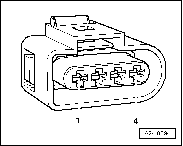
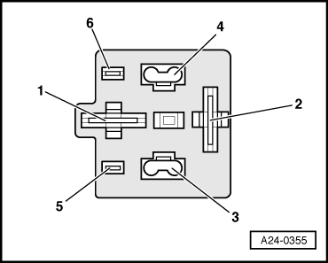
| Connector Contact | Measure to |
| 1 | Engine earth |
|
|
|
|
|
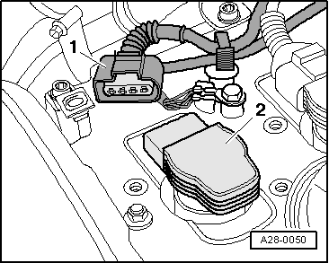
| Relay carrier beneath cover on left at bulkhead Contact | Connector at ignition coils Contact |
| 2 | 1 |
|
|
|
|
|
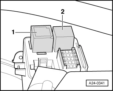
| Relay carrier beneath cover on left at bulkhead Contact | Measure to |
| 1 | Engine earth |
| 3 | Engine earth |
|
|
|
|
|
|
|
|
|
| Relay carrier beneath cover on left at bulkhead Contact | Measure to |
| 5 | Battery positive |
|
|
|
| Relay carrier beneath cover on left at bulkhead Contact | Test box -V.A.G 1598/31- Socket |
| 5 | 21 |
|