audi Workshop Repair Guides

Audi Workshop Service and Repair Manuals

Vacuum system layout > < Checking bus system
Communication takes place between three or more control units by way of a “two-wire bus system”.
–  Assess the faults stored in the control units.
  Note
Assessment helps to localise the wiring fault.
Example 1:
The faults entered in the fault memories indicate that there is no connection between control unit 1 and control units 2 and 3.
   
Control unitFaults entered in fault memory
1
t  No message from control unit 2
t  No message from control unit 3
2
t  No message from control unit 1
3
t  No message from control unit 1

–  Switch off ignition.
–  Disconnect the control units linked by the bus wires and check for open circuit in one of the bus wires. → Current flow diagrams, Electrical fault finding and Fitting locations
–  Replace control unit 1 if no faults are found in the bus wires.
Example 2:
The faults entered in the fault memories indicate that there is no connection between control unit 2 and control units 1 and 3.
   
Control unitFaults entered in fault memory
1
t  No message from control unit 2
2
t  No message from control unit 1
t  No message from control unit 3
3
t  No message from control unit 2

–  Switch off ignition.
–  Disconnect the control units linked by the bus wires and check for open circuit in one of the bus wires. → Current flow diagrams, Electrical fault finding and Fitting locations
–  Replace control unit 2 if no faults are found in the bus wires.
Example 3:
The faults entered in the fault memories indicate that none of the control units can transmit or receive.
   
Control unitFaults entered in fault memory
1
t  Drive system data bus defective
2
t  Drive system data bus defective
3
t  Drive system data bus defective

–  Switch off ignition.
   
–  Disconnect the control units linked by the bus wires and check the bus wires for short to positive and earth. → Current flow diagrams, Electrical fault finding and Fitting locations
If the cause of the fault “Drive system data bus defective” cannot be found in the bus wires, check whether one of the control units is responsible for the fault.
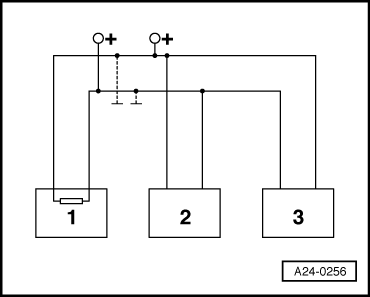
All control units using CAN bus for communication still disconnected; ignition switched off.
–  Connect one of the control units.
–  Connect the fault reader -V.A.G 1551-. Switch on the ignition and erase the fault memory of the control unit just connected. Terminate fault reader output with function 06 “End of output”.
–  Switch ignition off and on again.
–  Leave ignition switched on for 10 seconds. Then use the fault reader to read out the fault memory of the control unit just connected.
–  If the fault “Drive system data bus defective” is read out, replace the control unit just connected.
–  If the fault “Drive system data bus defective” is not read out, connect the next control unit and repeat the procedure.
  A24-0256

Vacuum system layout > < Checking bus system