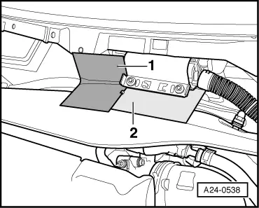
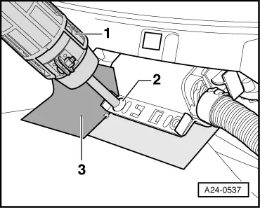
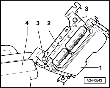
| To make it more difficult to pull out the engine control unit -1-, the locking element -2- is bolted onto the protective housing with the shear bolts -3-. |
| To make it even more difficult to screw out the shear bolts, the threads are coated with locking fluid. |
| –
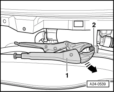
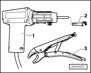
| Clamp the control unit in a vice |
| Installation is performed accordingly in the reverse sequence. |
| –
| The protective housing must always be re-attached to the engine control unit. |
| –
| Remove remnants of locking fluid from the tapped holes for the shear bolts. This can be done by using a thread tap. |
| –
| Always use new shear bolts. |
| –
| Bend back the retainer tab of the mount. |
| The following operations must be performed after connecting the new engine control unit: |
| –
| Perform adaption of throttle valve module -J338- → Chapter. |
| –
| Perform adaption of kick-down function for vehicles with automatic gearbox → Chapter. |
| –
| The immobilizer must be enabled using vehicle diagnostic and service information system -VAS 5052-. |
| –
| In “Guided Fault Finding” mode, “Select type” menu, select the option “Remaining vehicles for online immobiliser interface” and follow the instructions in Guided Fault Finding. |
|
|
|
 Note
Note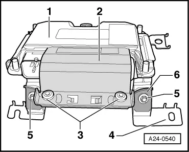
 WARNING