audi Workshop Repair Guides

Audi Workshop Service and Repair Manuals

Testing coolant temperature sender > < Testing intake air temperature sender (vehicles as of model year 1998)
Simos Injection and Ignition System (4-cylinder)
Testing ignition system
Testing engine speed sender

Note:

  • ◆ The engine speed sender is a combined speed sender and reference mark sender.
  • ◆ The engine can run without a signal from the -G28. It is also possible (with considerable difficulty) to start the engine without a signal from the -G28 (emergency running function).
  • ◆ For testing the operation of the engine speed sender, see also "Reading measured value block", Display Group 03, display zone 1.

Testing engine speed sender

Fitting location of sender and connector
.

  • ‒ Before carrying out the test, make sure that the sender is correctly installed and firmly seated.
  • ‒ Unplug connector for engine speed sender (grey connector).
 
A24-0089
  • ‒ → Connect hand held multimeter V.A.G 1526 (resistance test range) to contacts 2 and 3 on connector for engine speed sender using test lead from V.A.G 1594.

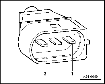
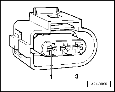
Specification: approx. 450...1000 ω.

  • ‒ If the value does not match the specification, fit a new engine speed sender.
  • ‒ If the value does match the specification, connect hand held multimeter to contacts 2 and 1 (earth) and to contacts 3 and 1 (earth).

Specification: infinite resistance (open circuit) in each test.

  • ‒ If the value does not match the specification, fit a new engine speed sender.
  • ‒ If the value does match the specification, test the wiring between the sender connector and the engine control unit as follows:
 
A24-0096
  • ‒ Connect test box V.A.G 1598/22 to wiring harness for engine control unit
    .
  • ‒ → Test continuity of screening from contact 1 on sender connector to socket 67 on test box.

Specification: max. 1 ω.

  • ‒ Test continuity of earth wire from contact 2 on sender connector to socket 63 on test box.

Specification: max. 1 ω.

  • ‒ Test continuity of signal wire from contact 3 on sender connector to socket 56 on test box.

Specification: max. 1 ω.

  • ‒ If the values are not as specified, rectify short or open circuit in wiring between sender connector and control unit connector.

Contact on sender connector

Contact on control unit connector

1
2
3

67
63
56

  • ‒ If no open circuits or short circuits are found, fit a new engine control unit .

Testing coolant temperature sender > < Testing intake air temperature sender (vehicles as of model year 1998)