audi Workshop Repair Guides

Audi Workshop Service and Repair Manuals

Testing engine speed sender > < Testing intake air temperature sender (vehicles up to model year 1998)
Simos Injection and Ignition System (4-cylinder)
Testing ignition system
Testing intake air temperature sender (vehicles as of model year 1998)

Note:

From model year 1998 onwards the intake air temperature sender (G42) is integrated in the air mass meter. The sender is therefore no longer fitted as a separate engine component.

  • ‒ Connect the fault reader V.A.G 1551 (V.A.G 1552). Then switch ignition on and select engine control unit with the "Address word" 01.
    (Connecting fault reader and selecting engine control unit .)
 
→ Display readout:
Rapid data transfer     HELP
Select function XX
  • ‒ Press keys 0 and 8 for the function "Read measured value block" and confirm entry with Q key.
 
→ Display readout:
Read measured value block    HELP
Enter display group number XXX
  • ‒ Press keys 0, 0 and 5 for "Display Group 5" and confirm entry by pressing Q.
 
→ Display readout:
(1...4 = display zones)
Read measured value block 5    ⇒
    1    2    3    4

Functional check of sender

  • ‒ Note intake air temperature figure in display zone 4.

Display

Cause

Continuation of test

60°C

Open circuit or short to positive

.

Short circuit to earth

approx. ambient temperature1)

---

.

    1)    If a temperature is displayed which deviates greatly from the ambient temperature of the sender, check sender wiring for contact resistances.

Continuation of check:

 
N24-0709
  • ‒ Switch off ignition.
  • ‒ → Connect test box V.A.G 1598/22 to wiring harness for control unit.

 
N24-0701
  • ‒ → Disconnect the 4-pin connector -1- from the air mass meter -2-.
  • ‒ Check wiring between test box and 4 pin connector for open circuit using current flow diagram.
        Contact 2+socket 12
        Contact 4+socket 9
        Wire resistance: max. 1.5 ω
  • ‒ Additionally check wires for short to one another.
        Specification: infinite resistance.

If no fault in wire is detected:

 
N24-0747
  • ‒ → Test resistance between contacts 2 and 4 of sender.

 
N24-0157

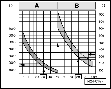
→ Scale A shows resistance values for temperature range 0...50 °C and scale B the values for temperature range 50...100 °C.

Examples:

  • ◆ 30 °C corresponds to a resistance of 1500...2000 ω
  • ◆ 80 °C corresponds to a resistance of 275...375 ω

If the specification is not attained:

  • ‒ Replace the air mass meter (G70) and the intake air temperature sender (G42).

Continuation of check if display = ambient temperature:

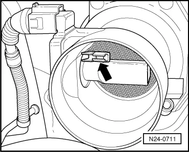
  • ‒ Remove the intake hose between air mass meter and throttle valve control unit.
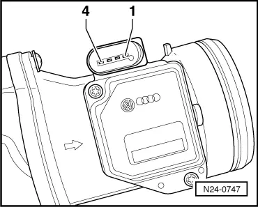
  • ‒ Note intake air temperature value in display zone 4.
 
N24-0711
  • ‒ → Spray sender -arrow- with commercial chilling agent whilst observing the temperature value. The temperature value should
        decrease.
  • ‒ Press the ⇒-key.
  • ‒ Press keys 0 and 6 for the function "End output" and confirm entry with the Q key.

Testing engine speed sender > < Testing intake air temperature sender (vehicles up to model year 1998)