audi Workshop Repair Guides

Audi Workshop Service and Repair Manuals

Testing air mass meter (vehicles up to model year 1998) > < Testing injection quantity, leak tightness and spray pattern of injectors
Simos Injection and Ignition System (4-cylinder)
Servicing Simos injection system
Testing fuel pump relay and activation
 
A24-0100

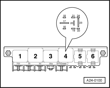
Note:

→ The fuel pump relay is located in the central electrics in the left hand footwell, relay position 4.

A - Testing fuel pump relay -J17

  • ‒ Remove storage bin in front left hand footwell.

 
A97-0022
  • ‒ → Remove fuel pump fuse from fuse holder and connect diode test lamp V.A.G 1527 between earth and one of the two contacts for the fuel pump fuse.

=> Current Flow Diagrams, Electrical Fault Finding and Fitting Locations

  • ‒ Operate the starter briefly.

The fuel pump relay should pick up (can be felt and heard) and the diode test lamp should light up.

  • ‒ If the fuel pump relay does not pick up, test activation .
  • ‒ If the fuel pump relay picks up but the diode test lamp does not light up, repeat the test on the other contact.
 
A24-0100
  • ‒ → If the diode test lamp still does not light up, test for open circuit in wiring between fuel pump fuse and contact 23 in relay position 4. If necessary, rectify open circuit.

=> Current Flow Diagrams, Electrical Fault Finding and Fitting Locations

  • ‒ If the power supply, activation and wiring for the fuel pump relay are OK, fit a new fuel pump relay.

B - Testing power supply and activation of fuel pump relay

Note:

Activation of the fuel pump relay can also be tested using the final control diagnosis.

=>Page01-52.

  • ‒ Remove fuel pump relay J17 from central electrics, relay position 4.

Testing power supply

  • ‒ Switch the ignition on.
 
A24-0100
  • ‒ → Connect hand-held multimeter V.A.G 1526 between earth and relay panel contact 19 (positive; terminal 15 from ignition switch). Disconnect, then re connect between earth and relay panel contact 17 (permanent positive; terminal 30 from battery).

Specification: approx. battery voltage in each case

  • ‒ If the values are not as specified, rectify the open circuit.

=> Current Flow Diagrams, Electrical Fault Finding and Fitting Locations

 
A24-0100

Testing activation

  • ‒ → Connect diode test lamp V.A.G 1527 between positive and contact 16 on relay panel (earth connection via engine control unit).
  • ‒ Operate the starter briefly.
  • ‒ The diode test lamp should light up and remain lit when the starter is operated.

Note:

 
A28-0022

Diode test lamps with a low current draw do not go out completely but continue to glow faintly until the starter is operated.

  • ‒ If the activation, wiring and power supply for the fuel pump relay are OK but the fuel pump relay still does not pick up, fit a new fuel pump relay.

If the diode test lamp does not light up, test the wiring as follows:

  • ‒ → Connect test box V.A.G 1598/22 to wiring harness for engine control unit
    .
  • ‒ Connect hand-held multimeter between contact 16 on relay panel and socket 4 on the test box, then test wiring for open circuits.
  • ‒ Rectify open circuit if necessary

=> Current Flow Diagrams, Electrical Fault Finding and Fitting Locations

  • ‒ If there is no open circuit and the diode test lamp still does not light up, fit a new engine control unit
    .
  • ‒ Refit the fuel pump fuse.

Testing air mass meter (vehicles up to model year 1998) > < Testing injection quantity, leak tightness and spray pattern of injectors