audi Workshop Repair Guides

Audi Workshop Service and Repair Manuals

Testing intake manifold changeover function > < Testing throttle valve positioner sender and throttle valve potentiometer
Simos Injection and Ignition System (4-cylinder)
Testing throttle valve control unit
Testing throttle valve control unit (vehicles as of model year 1998)

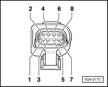
Perform the adaptation as before.

.

Components of the throttle valve control unit (J338):
Throttle valve positioner (V60), throttle valve positioner potentiometer (G88), throttle valve potentiometer (G69) and idling switch (F60)

Note:

If the throttle valve control unit is replaced, the following must be carried out:

  • ◆ adapt the engine control unit to the throttle valve control unit .
  • ◆ On vehicles with an automatic gearbox: Adapt the gearbox control unit

=> Automatic gearbox 01M 4-speed, Self-diagnosis; Repair Group 01; Carry out self-diagnosis; Start basic setting

Contact pin assignment of throttle valve control unit differs on vehicles with or without a cruise control system (CCS).

Identification: Steering column switch with controls for CCS.

Note:

On vehicles equipped with cruise control (CCS) the throttle valve positioner can open the throttle valve throughout the entire engine speed range.

Test conditions

  • ● Earth connection between throttle valve control unit and cylinder head OK.
  • ● Throttle valve not damaged or dirty.

Testing idling switch

  • ‒ Connect the fault reader V.A.G 1551 (V.A.G 1552). Then switch ignition on and select engine control unit with the "Address word" 01.
    (Connecting fault reader and selecting engine control unit => Page 01-4.)
 
→ Display readout:
Rapid data transfer     HELP
Select function XX
  • ‒ Press keys 0 and 8 for the function "Read measured value block" and confirm entry with Q key.
 
→ Display readout:
Read measured value block    HELP
Enter display group number XXX
  • ‒ Press keys 0, 9 and 8 for "Display Group 98" and confirm entry by pressing Q key.
 
→ Display readout:
(1...4 = display zones)
Read measured value block 98    ⇒
    1    2    3    4
  • ‒ Check idling switch at idling stop in display zone 3.
  • 1st position from right must display 0
        Display: 00000000
  • ‒ Gradually open throttle valve.
  • 1st position from right must display 1
        Display: 00000001

If the specifications are not obtained:

Display

Cause

Continuation of test

Always 1

Open circuit or short to positive

.

Always 0

Short circuit to earth

.

Continuation of test if display constantly shows 1

 
N24-0170
  • ‒ → Pull 8-pin connector off throttle valve control unit.
  • ‒ Bridge the following contacts:
        Vehicles with CCS1): Contacts 2 + 6
        Vehicles without CCS1): Contacts 3 + 7
    using auxiliary cables from V.A.G 1594 and observe display.

    1)    CCS = cruise control system

Display 0:

  • ‒ Press the ⇒key.
  • ‒ Press keys 0 and 6 for the function "End data transfer" and confirm entry with the Q key.
  • ‒ Switch off ignition.
  • ‒ Fit a new throttle valve control unit
  • ‒ Perform adaptation => Page 24-69.

Display 1:

  • ‒ Press the ⇒key.
  • ‒ Press keys 0 and 6 for the function "End data transfer" and confirm entry with the Q key.
  • ‒ Switch off ignition.
  • ‒ Check voltage supply of throttle valve control unit and wiring to control unit => Page 24-95.

If the voltage supply and wiring is OK:

  • ‒ Fit a new engine control unit => Page 24-10.

Continuation of test if display constantly shows 0

 
N24-0170
  • ‒ → Pull 8-pin connector off throttle valve control unit.

Display 1:

  • ‒ Press the ⇒key.
  • ‒ Press keys 0 and 6 for the function "End data transfer" and confirm entry with the Q key.
  • ‒ Switch off ignition.
  • ‒ Fit a new throttle valve control unit
  • ‒ Perform adaptation => Page 24-69.

Display 0:

  • ‒ Press the ⇒key.
  • ‒ Press keys 0 and 6 for the function "End data transfer" and confirm entry with the Q key.
  • ‒ Switch off ignition.
  • ‒ Check voltage supply of throttle valve control unit and wiring to control unit => Page 24-95.

If the voltage supply and wiring is OK:

  • ‒ Fit a new engine control unit => Page 24-10.

Checking operating condition

  • ‒ Connect the fault reader V.A.G 1551 (V.A.G 1552). Start the engine and select the engine control unit with "Address word" 01.
    (Connecting fault reader and selecting engine control unit => Page 01-4.)
 
→ Display readout:
Rapid data transfer     HELP
Select function XX
  • ‒ Press keys 0 and 8 for the function "Read measured value block" and confirm entry with Q key.
 
→ Display readout:
Read measured value block    HELP
Enter display group number XXX
  • ‒ Press keys 0, 9 and 8 for "Display Group 98" and confirm entry by pressing Q key.
 
→ Display readout:
(1...4 = display zones)
Read measured value block 98    ⇒
    1    2    3    4
  • ‒ Check throttle valve control unit operating condition in display zone 3.
        Specification: 00000000

Relevance of figures in 8 digit number block for throttle valve control unit operating status:

x

x

x

x

x

x

x

x

"1" signifies:

0

Not allocated

0

Not allocated

0

Not allocated

0

Not allocated

1

A fault has occurred during the adaptation of the throttle valve (interrogate fault memory
)

1

No current supply to throttle valve control unit (signal ratio = 0)

1

Adaptation interrupted due to the battery voltage being too low (below 8V).

1

Idling switch open (switch position check)

If the specifications are not obtained:

  • ‒ Adapt the engine control unit to the throttle valve control unit => Page 24-69.
  • ‒ Repeat check.

If the specifications are still not attained:

  • ‒ Check voltage supply of throttle valve control unit and wiring to control unit => Page 24-95.

Checking throttle valve potentiometer

Test conditions

  • ● Coolant temperature at least 80 °C
  • ‒ Connect the fault reader V.A.G 1551 (V.A.G 1552). Then switch ignition on and select engine control unit with the "Address word" 01.
    (Connecting fault reader and selecting engine control unit => Page 01-4.)
 
→ Display readout:
Rapid data transfer     HELP
Select function XX
  • ‒ Press keys 0 and 8 for the function "Read measured value block" and confirm entry with Q key.
 
→ Display readout:
Read measured value block    HELP
Enter display group number XXX
  • ‒ Press keys 0, 0 and 1 for "Display Group 1" and confirm entry by pressing Q. key.
 
→ Display readout:
(1...4 = display zones)
Read measured value block 1    
    1    2    3    4
  • ‒ Check whether the coolant temperature is above 80 °C in display zone 2.
  • ‒ Change to display group 3 as follows:
  • ‒ Press C key.
 
→ Display readout:
Read measured value block    HELP
Enter display group number XXX
  • ‒ Press keys 0, 0 and 3 for "Display Group 3" and confirm entry by pressing Q.
 
→ Display readout:
(1...4 = display zones)
Read measured value block 3    
    1    2    3    4
  • ‒ Read off throttle valve angle in display zone 3.
        Specification: 1,9...5,7 <°
  • ‒ Slowly open throttle valve and watch angle display in display zone 3.
    The figure must increase uniformly over
        the complete range.
  • ‒ Press the ⇒key.
  • ‒ Press keys 0 and 6 for the function "End output" and confirm entry with the Q key.
  • ‒ Switch off ignition.

If the figure does not increase uniformly:

  • ‒ Fit a new throttle valve control unit
  • ‒ Perform adaptation => Page 24-69.

If the display remains constant:

  • ‒ Check voltage supply of throttle valve control unit and wiring to control unit => Page 24-95.

Checking throttle valve positioner and throttle valve positioner potentiometer

Test conditions

  • ● Coolant temperature at least 80 °C.
  • ‒ Connect the fault reader V.A.G 1551 (V.A.G 1552). Start the engine and select the engine control unit with "Address word" 01.
    (Connecting fault reader and selecting engine control unit => Page 01-4.)
 
→ Display readout:
Rapid data transfer     HELP
Select function XX
  • ‒ Press keys 0 and 8 for the function "Read measured value block" and confirm entry with Q key.
 
→ Display readout:
Read measured value block    HELP
Enter display group number XXX
  • ‒ Press keys 0, 0 and 1 for "Display Group 1" and confirm entry by pressing Q.
 
→ Display readout:
(1...4 = display zones)
Read measured value block 1    ⇒
    1    2    3    4
  • ‒ Check whether the coolant temperature is above 80 °C in display zone 2.
  • ‒ Change to display group 98 as follows:
  • ‒ Press C key.
 
→ Display readout:
Read measured value block    HELP
Enter display group number XXX
  • ‒ Press keys 0, 9 and 8 for "Display Group 98" and confirm entry by pressing Q.
 
→ Display readout:
(1...4 = display zones)
Read measured value block 98    ⇒
    1    2    3    4
  • ‒ Check the voltage value of the throttle valve positioner potentiometer in display zone 2.
        Specification: 2.28...4.75 V

If the specification is not attained:

  • ‒ Press the ⇒key.
  • ‒ Press keys 0 and 6 for the function "End data transfer" and confirm entry with the Q key.
  • ‒ Switch off ignition.
 
N24-0170
  • ‒ Remove the intake hose.
  • ‒ → Pull 8-pin connector off throttle valve control unit.
  • ‒ Measure resistance of throttle valve positioner between following contacts:
        Vehicles with CCS1): Contacts 7 + 8
        Vehicles without CCS1): Contacts 1 + 2
        Specification: 3...200 ω

    1)    CCS = cruise control system

If the specification is not attained:

  • ‒ Fit a new throttle valve control unit
  • ‒ Perform adaptation => Page 24-69.

If the specification is attained:

  • ‒ Check voltage supply of throttle valve control unit and wiring to control unit => Page 24-95.

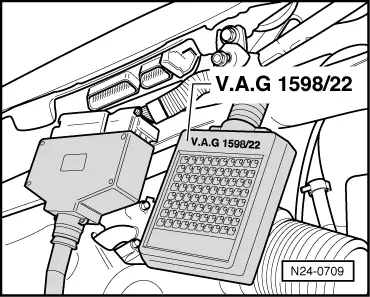
Checking voltage supply and wiring to control unit

 
N24-0170
  • ‒ → Pull 8-pin connector off throttle valve control unit.
  • ‒ Connect multimeter to measure voltage at following connector contacts:
        Vehicles with CCS1): Contacts 2 + 5
        Vehicles without CCS1): Contacts 4 + 7

    1)    CCS = cruise control system

  • ‒ Switch the ignition on.
        Specification: at least 4.5 V
  • ‒ Switch off ignition.
  • ‒ Connect multimeter to measure voltage at following connector contacts:
        Vehicles with CCS1): Contacts 2 + 6
        Vehicles without CCS1): Contacts 3 + 7

    1)    CCS = cruise control system

  • ‒ Switch the ignition on.
        Specification: at least 9 V
  • ‒ Switch off ignition.
 
N24-0709
  • ‒ → Connect test box V.A.G 1598/22 to wiring harness for control unit.

 
N24-0170
  • ‒ → Check wiring between test box and connector for open circuit using current flow diagram.

Vehicles fitted with cruise control system:
    Contact 1+socket 74
    Contact 2+socket 70
    Contact 4+socket 75
    Contact 5+socket 62
    Contact 6+socket 69
    Contact 7+socket 59
    Contact 8+socket 66
    Wire resistance: max. 1.5 ω

Vehicles without cruise control system:
    Contact 1+socket 66
    Contact 2+socket 59
    Contact 3+socket 69
    Contact 4+socket 62
    Contact 5+socket 75
    Contact 7+socket 70
    Contact 8+socket 74
    Wire resistance: max. 1.5 ω

  • ‒ Additionally check wires for short to one another.
        Specification: infinite resistance.

If no wiring fault is detected:

  • ‒ Test the power supply to the engine control unit => Page 28-23.

Testing intake manifold changeover function > < Testing throttle valve positioner sender and throttle valve potentiometer