audi Workshop Repair Guides

Audi Workshop Service and Repair Manuals

Replacing control unit for engine electronics > < Replacing the O-ring on the injection timing device cover
TDI Injection and Glow Plug System (4-cyl.) 08.99 >
Servicing diesel direct injection system
Wiring and component check with test box V.A.G 1598/31

The following procedure applies to engine control units not fitted with a locking device (anti-theft protection). The procedure for engine control units with locking device can be found on .

Notes:

  • ◆ The test box V.A.G 1598/31 is designed in such a way that it can be connected simultaneously to the engine control unit wiring harness and to the engine control unit itself.
  • ◆ This has the advantage that the electronic engine control system remains fully functional when the test box is connected (for example, for measuring signals when the engine is running).
  • ◆ Whether the engine control unit has to be additionally connected to the test box or not is described in the respective test procedures.
  • ◆ Always use adapter set V.A.G 1594 A for connecting up measuring instruments (e.g. voltage tester V.A.G 1527 B, hand-held multimeter V.A.G 1526 A etc.).
Important
To prevent damage to the electronic components, select appropriate measuring range before connecting the measuring cables and observe the test requirements.
 
W00-0943

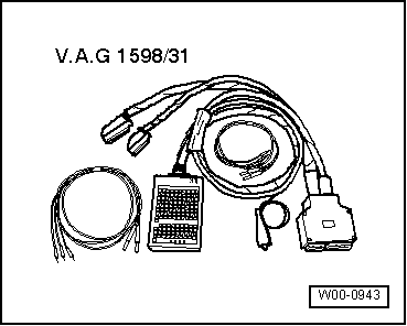
Special tools and workshop equipment required

  • ◆ V.A.G 1598/31

Procedure

  • ‒ Switch ignition off.
  • ‒ Remove engine control unit => Page 23-42.
 
A24-0198
  • ‒ → Connect V.A.G 1598/31 test box to connectors of wiring harness. The earth clip on the test box (not visible in the illustration) must be connected to earth. Whether or not the engine control unit has to be additionally connected to the test box is described in the respective test procedures.
  • ‒ Carry out test as described in the appropriate repair procedures.

Perform the following operations after re-connection of engine control unit:

  • ‒ Interrogate fault memory and erase, if necessary.

The following procedure applies to engine control units fitted with a sheet-metal housing (anti-theft protection).

Notes:

  • ◆ The test box V.A.G 1598/31 is designed in such a way that it can be connected simultaneously to the engine control unit wiring harness and to the engine control unit itself.
  • ◆ This has the advantage that the electronic engine control system remains fully functional when the test box is connected (for example, for measuring signals when the engine is running).
  • ◆ Whether the engine control unit has to be additionally connected to the test box or not is described in the respective test procedures.
  • ◆ Always use adapter set V.A.G 1594 A for connecting up measuring instruments (e.g. voltage tester V.A.G 1527 B, hand-held multimeter V.A.G 1526 A etc.).

Procedure

  • ‒ Switch ignition off.
  • ‒ Unscrew the windscreen wiper arms.
  • ‒ Remove the plenum chamber cover and lay aside towards the windscreen.
 
A24-0540

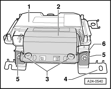
Note:

Item -1- in the illustration shows the engine control unit with protective housing.

 
A24-0540

→ To make access to the engine control unit connectors more difficult (anti-theft protection), the engine control unit -1- is fitted with a sheet-metal housing -4- via locking device -2- and shear bolts -3-.

The thread of the shear bolts is coated with locking compound to make removal of the shear bolts especially difficult.

If the connectors are to be unplugged from the engine control unit (e.g. to connect a test box), the locking device -2- must be detached from the sheet-metal housing. This procedure is described below.

 
A24-0475

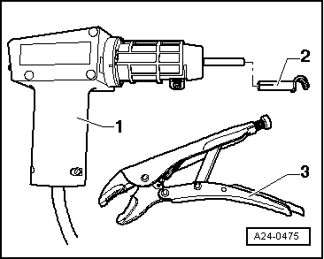
The following tools are needed:

  • ◆ → Hot air blower -1- (from wiring harness repair set VAS 1978)
  • ◆ A commercially-available vice-grip wrench

Procedure:

Important
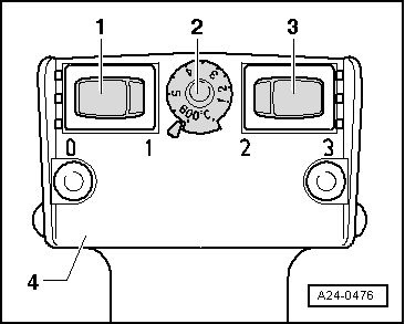
The following steps must be followed exactly to prevent any damage (burning) to wiring, connectors, insulation and control units. Note the hot air blower operating instructions.
 
A24-0538

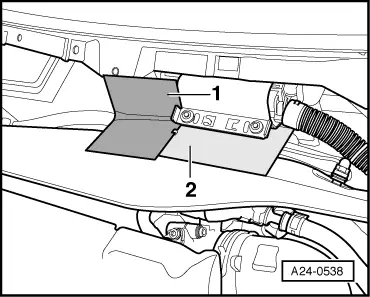
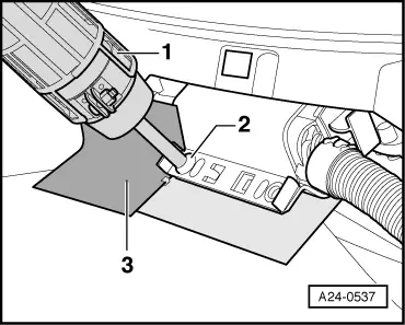
→ To prevent damage to wiring and connectors, make a screen using metal plates (Items -1- and -2-).
This should prevent the connector housing
and the wiring harness from becoming hot.

 
A24-0476
  • ‒ → Adjust the hot air blower settings as illustrated, i.e. set the temperature setting potentiometer -2- to maximum heating output and the two-speed switch for air volume -3- to position 3.

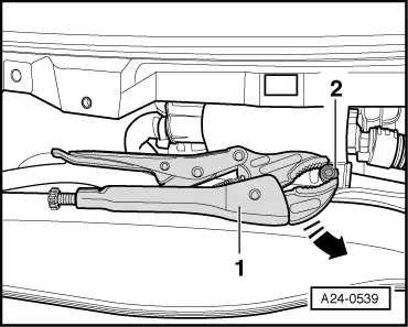
Note:

The bolt of the locking device is then heated with the hot air blower. This step diminishes the bonding effect of the locking compound on the thread of the shear bolts, and it is then easier to unscrew the shear bolts.

Important
The shear bolts and sheet-metal housing components also become very hot when the thread of the locking device is being heated. Take care not to burn yourself on them. Ensure that as far as possible it is only the thread that is heated and none of the nearby components. If necessary, these should be covered.
 
A24-0537
  • ‒ → Direct the nozzle -1- of the hot air blower onto the bolt -2- of the locking device.

Note:

Be especially careful here, because the control unit connectors are extremely near.

  • ‒ Switch on the hot air blower and heat the thread for approximately 20 to 25 seconds.

 
A24-0539
  • ‒ → Then grip the bolt head -2- with the vice-grip wrench -1- and unscrew the shear bolt in the direction of the arrow.
  • ‒ To give increased anti-theft protection, the locking device has been installed so that a full turn with the vice-grip wrench is impossible.

The procedure for the second shear bolt is exactly the same. Be especially careful here, because the control unit connectors are extremely near.

  • ‒ The connector locking device can be removed once the second bolt has been removed.
  • ‒ Release the connector latches and detach the control unit connectors.
 
A24-0198
  • ‒ → Connect V.A.G 1598/31 test box to connectors of wiring harness. The earth clip on the test box (not visible in the illustration) must be connected to earth. Whether or not the engine control unit has to be additionally connected to the test box is described in the respective test procedures.
  • ‒ Carry out test as described in the appropriate repair procedures.

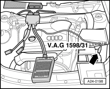
Perform the following operations after re-connection of engine control unit:

Installation is carried out in reverse order to removal, and the sheet-metal housing (locking device) is refitted on the engine control unit. New shear bolts must be used.

  • ‒ Interrogate fault memory and erase, if necessary.

Replacing control unit for engine electronics > < Replacing the O-ring on the injection timing device cover