
A3 Mk1
|
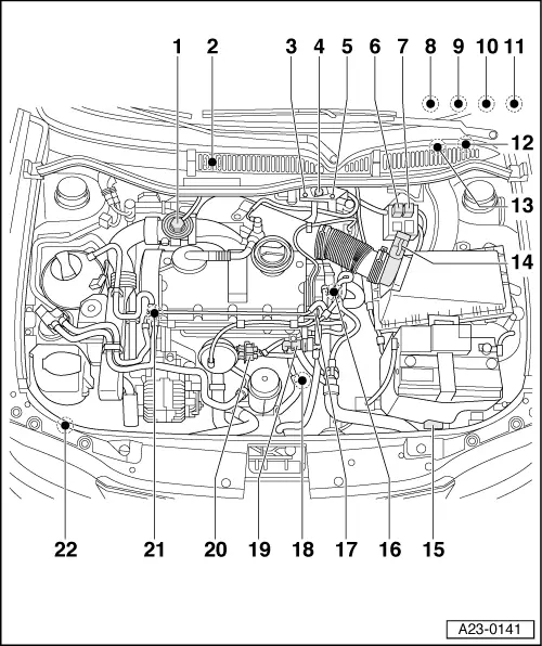
Servicing Diesel direct injection system
Fitting locations overview
|
 |
|
|
|
|
 |
|
|
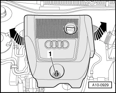
→ Fig.1 Removing engine cover
|
 |
|
|
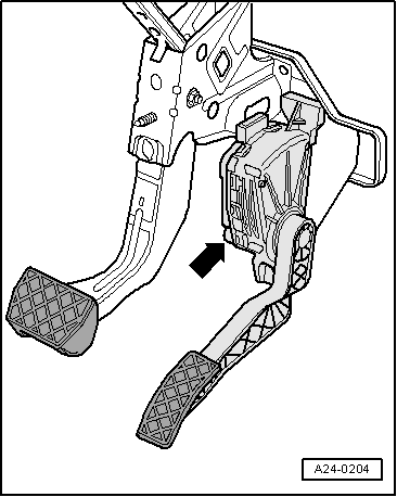
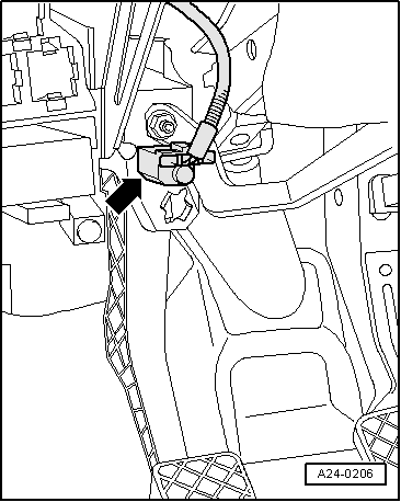
→ Fig.2 Fitting location of accelerator position sender -G79 Note: Illustration shows arrangement on LHD vehicles |
 |
|
|
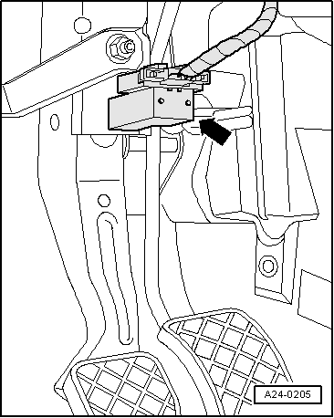
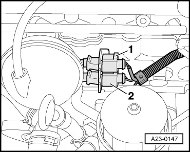
→ Fig.3 Fitting location of brake light switch -F and brake pedal switch -F47 |
 |
|
|
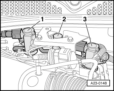
→ Fig.4 Fitting locations of 3-pin connectors
|
 |
|
|
→ Fig.5 Fitting location of clutch pedal switch -F36 |
 |
|
|
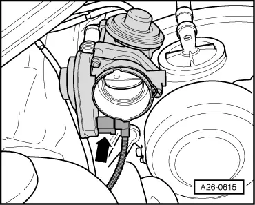
→ Fig.6 Fitting location for intake manifold flap motor -V157 (engine with code letters AXR) |
 |
|
|
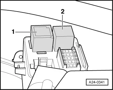
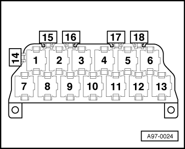
→ Fig.8 Fitting location for low heat output relay -J359 and high heat output relay -J360
|
 |
|
|
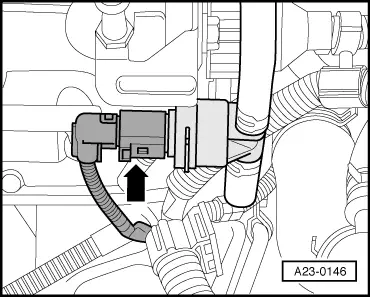
→ Fig.9 Fitting location of fuel temperature sender -G81
|
 |
|
|
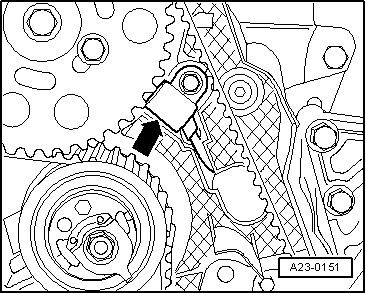
→ Fig.10 Fitting location for Hall sender -G40
|
 |
|
|
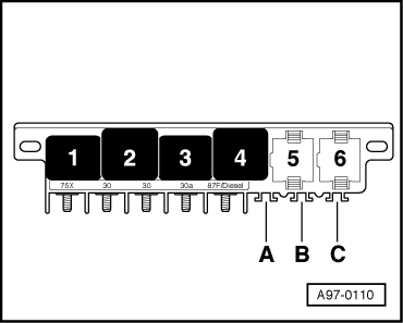
→ Fig.11 Fitting location for glow plug relay -J52
|
 |
|
|
→ Fig.12 Fitting location for diesel direct injection system relay -J322
|