
A3 Mk1
|
Servicing Diesel direct injection system
Renewing engine control unit with protective housing
|
 |
|
|
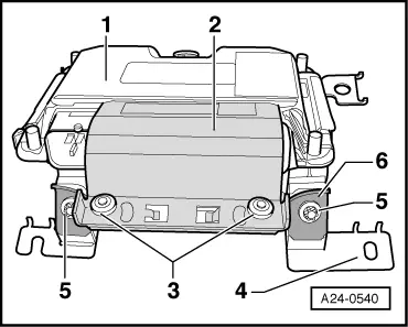
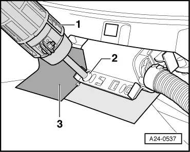
→ The engine control unit -1- is secured with a locking plate -2- and shear bolts -3- to a protective housing -4-. The threads of the bolts are coated with a locking compound. The engine control unit must be separated from the protective housing in order to detach the connectors from the control unit (for example, when connecting the test box or replacing the engine control unit). |
 |
|
|
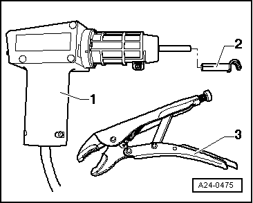
Special tools and workshop equipment required
|
 |
|
|
 |
|
|
Removing
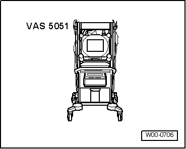
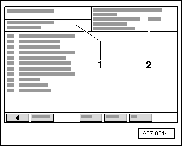
→ The display on vehicle diagnostic, test and information system VAS 5051 will show the control unit identification and the coding -2-.
|
 |
|
|
 |
|
|
Caution
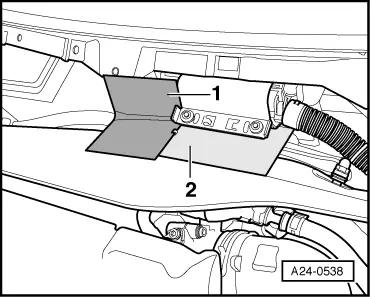
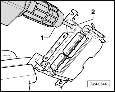
Keep exactly to the following procedure to avoid damage (burning) to the wiring, connectors, insulation or the control units. Follow the operating instructions supplied with the hot-air blower. → In order to avoid damaging wiring and connectors, you must fashion a shield -item 1 and 2- with sheet metal or similar. This is to prevent overheating of the connector housing and wiring harness. |
 |
|
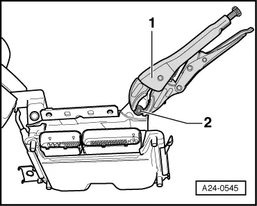
Note: Thereafter, heat the screw base on locking plate, in which the shear bolts are located. This step reduces the locking effect of the compound on the shear bolt threading, which enables easier removal of the bolts. |
 |
|
|
As a result of the warming process, the shear bolts and parts of the metal housing will also be very hot. Take care to avoid burns! If possible, heat only the thread base and not other nearby sensitive components - cover such parts if needed.
Note: Be especially careful here, since control unit connectors are located in the immediate vicinity.
|
 |
|
The procedure is the same for the second shear bolt. Note: Be especially careful here, since control unit connectors are located in the immediate vicinity.
|
 |
|
|
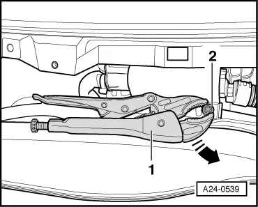
The control unit must not be pulled over the locking plate - this can place the control unit under tension and cause damage! → The locking plate -2- must only be unscrewed from mounting bracket after the whole unit is removed. The control unit can be only pulled out after the shear bolts -3- have been unscrewed from the locking plate!
|
|
|
|
Caution
Keep exactly to the following procedure to avoid damage (burning) to the wiring, connectors, insulation or the control units. Follow the operating instructions supplied with the hot-air blower.
Note: Thereafter, heat the screw base on locking plate, in which the shear bolts are located. This step reduces the locking effect of the compound on the shear bolt threading, which enables easier removal of the bolts. |
 |
|
|
As a result of the warming process, the shear bolts and parts of the metal housing will also be very hot. Take care to avoid burns! If possible, heat only the thread base and not other nearby sensitive components - cover such parts if needed.
|
 |
|
The procedure is the same for the second shear bolt. The engine control unit can now be removed from the metal housing. Installing Installation is performed in the reverse sequence; the engine control unit is placed back into protective housing and new shear bolts are to be used.
Note: After installing the new engine control unit the following operations must be performed:
|