audi Workshop Repair Guides

Audi Workshop Service and Repair Manuals

Checking brake light switch -F and brake pedal switch -F47 > < Testing intake manifold pressure sender -G71 and altitude sender -F96
TDI®injection and glow plug system (4-cyl. unit injector)
Testing control unit input values
Testing coolant temperature sender -G62

Fitting location => Fitting locations overview, Page 23-4

Test requirement:

  • ● Engine cold
 
A01-0139

Test sequence

  • ‒ Read data block, Display group 007, engine cold and running at idling speed=>Page 01-131

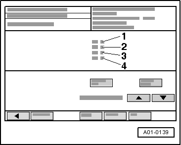
→ Display on VAS 5051:

  • ‒ Check readout in display zone -4-.
    • ‒ Specification: The temperature value should increase steadily.

Note:

In case of a fault, the fuel temperature will be displayed.

If the fuel temperature display is defective as well, a constant temperature of -5.4°C will be displayed.

  • ‒ Press the ◂ button to exit from the function "08 - Read data block".
  • ‒ Select diagnosis function "06 - End output".
  • ‒ Switch off ignition.
 
N24-1019

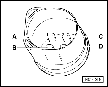
If an implausible value is displayed in display zone 4:

Testing internal resistance

  • ‒ Unplug 4 pin connector from coolant temperature sender G62.
  • ‒ → Connect multimeter (resistance test range) between contacts C and D on the sender.

 
N24-0157

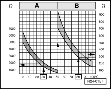
Scale A shows resistance values for temperature range 0...50 °C and scale B the values for temperature range 50...100 °C.

→ Examples:

  • ◆ 30 °C corresponds to a resistance from 1500...2000 ω
  • ◆ 80 °C corresponds to a resistance from 275...375 ω

If the specification is not attained:

  • ‒ Fit a new coolant temperature sender.

If the specification is obtained:

Checking wiring connections

  • ‒ Connect test box V.A.G 1598/31 to wiring harness for engine control unit.Do notconnect to the engine control unit itself:
    • ‒ Connecting test box to engine control unit without protective housing=>Page 23-49.
    • ‒ Connecting test box to engine control unit with protective housing=>Page 23-51.
 
A24-0274
  • ‒ → Test for open circuit and short to positive or earth in the following wiring connections:

Connector
Contact

Test box V.A.G 1598/31
Socket

3

112

4

104

  • ‒ Test for short circuits between the two wires.
  • ‒ Rectify any open/short circuit as necessary.

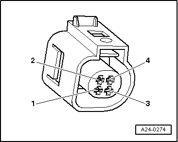
If no fault is found:

  • ‒ Replace engine control unit
    • ‒ Removing and installing engine control unit without protective housing=>Page 23-57.
    • ‒ Removing and installing engine control unit with protective housing=>Page 23-60.

Checking brake light switch -F and brake pedal switch -F47 > < Testing intake manifold pressure sender -G71 and altitude sender -F96