
A3 Mk1
 |
|
|
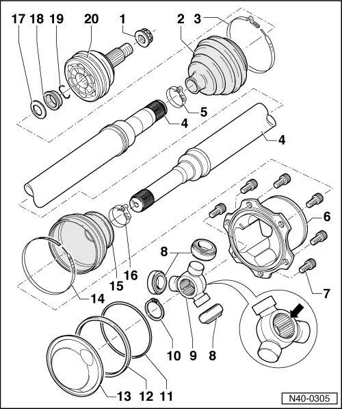
Exploded view of components
|
|
|
|
|
|
|
 |
|
|
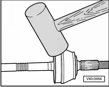
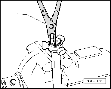
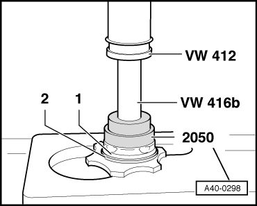
→ Fig.1 Removing outer constant velocity joint
|
 |
|
|
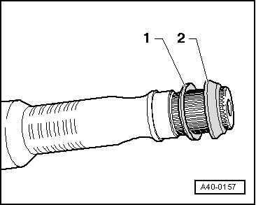
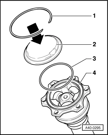
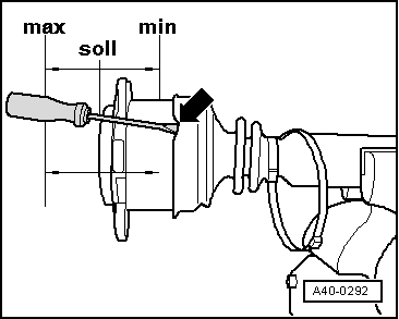
Fig.2 → Installation position of spacer ring and dished washer
|
 |
|
|
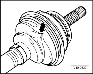
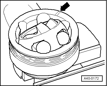
→ Fig.3 Venting rubber boot Boot is often squashed on positioning it on joint housing. This produces a vacuum in the boot, which causes a fold to form whilst driving -arrow-. Attention is therefore to be paid to the following:
|
 |
|
|
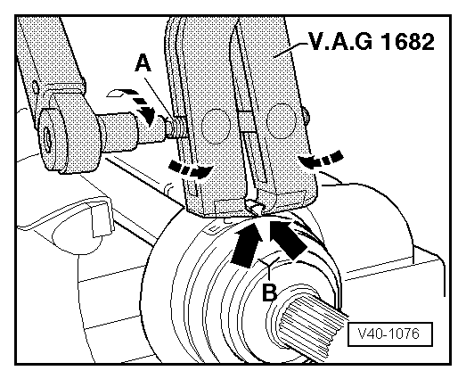
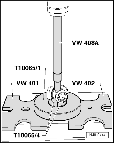
→ Fig.4 Tensioning large clamp for rubber boot |
 |
|
|
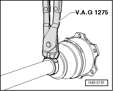
→ Fig.5 Tensioning stainless-steel clamps for Hytrel boots
Notes:
|
 |
|
|
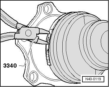
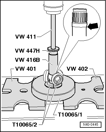
→ Fig.6 Tensioning small clamp for rubber boot |
 |
|
|
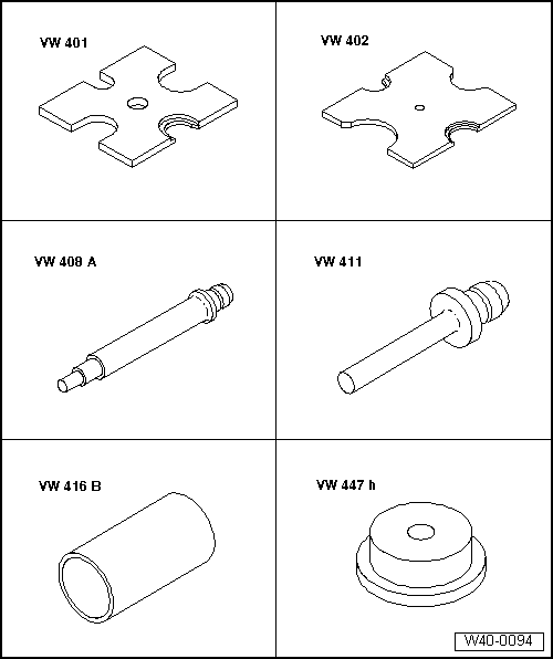
Dismantling and assembling triple roller joint AAR 2900 Special tools and workshop equipment required
|
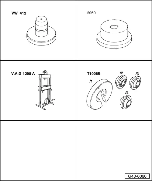 |
|
|
 |
|
|
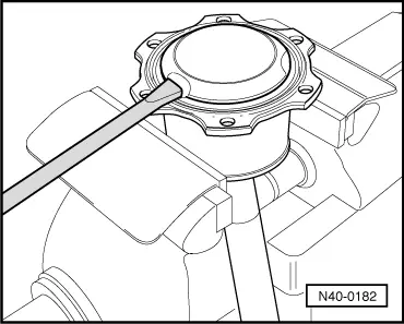
Dismantling
|
 |
|
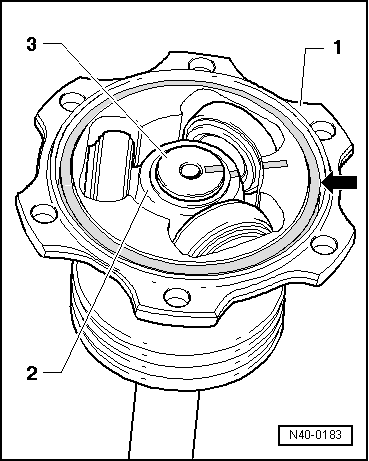
Notes:
Note: Make sure rollers do not slide off triple roller star and drop onto ground.
|
 |
|
|
 |
|
|
 |
|
|
 |
|
|
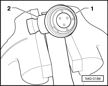
Assembling
Fitting triple roller star
|
 |
|
|
 |
|
|
 |
|
|
 |
|
|
Checking outer constant velocity joint The joint must be dismantled for replacing grease in the event of severe contamination or if ball contact surfaces are to be checked for wear and damage. Removing
|
 |
|
|
 |
|
Notes:
Installing Install in reverse order, paying attention to the following:
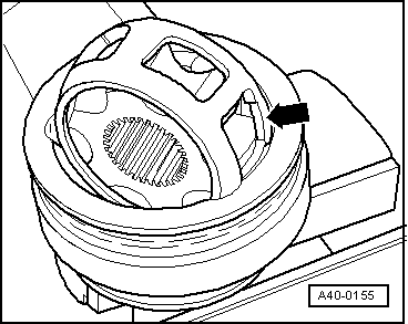
Note: Cage must be inserted in correct position.
|