
A3 Mk1
|
Wheel bearing housing
Replacing front wheel bearing with wheel bearing housing fitted
|
 |
|
Sequence of operations
|
 |
|
|
Four-wheel drive vehicles:
All models:
|
 |
|
|
 |
|
|
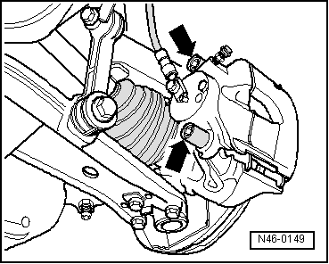
Vehicles with brake caliper FS 3:
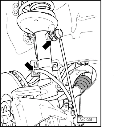
Note: Brake hose/pipe is never to be twisted or kinked. |
 |
|
|
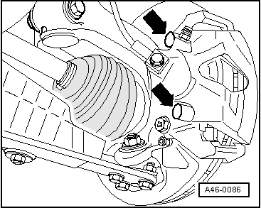
Vehicles with brake caliper FN 3:
|
 |
|
Note: Brake hose/pipe is never to be twisted or kinked. All models:
|
 |
|
|
Audi A3:
|
 |
|
|
Audi S3:
|
 |
|
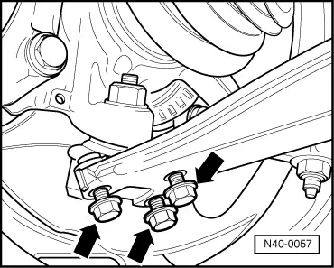
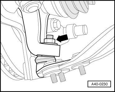
Note: Leave nut screwed several turns onto ball joint to protect thread.
Attention:
On pressing out, ball joint is abruptly released from wheel bearing housing and can be a source of danger. |
 |
|
|
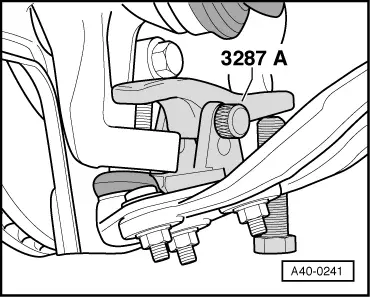
All models:
Note: Ensure adequate clearance when pressing out drive shaft.
Note: Failure to tie drive shaft in position would damage inner joint. |
 |
|
|
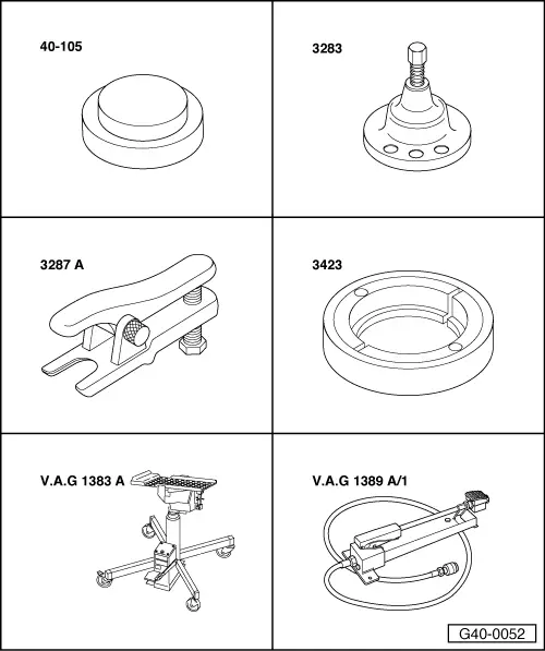
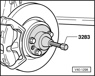
Pressing out wheel hub Attention:
Place engine/gearbox lifter V.A.G 1383
|
 |
|
|
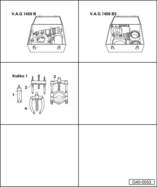
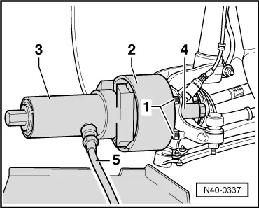
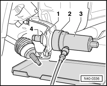
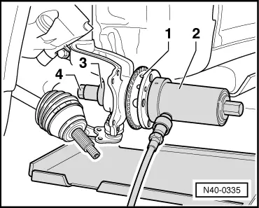
Pressing out wheel bearing
|
 |
|
|
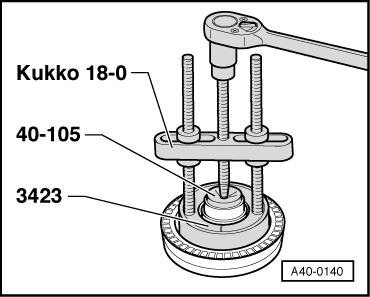
Detaching bearing inner race from wheel hub
|
 |
|
|
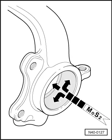
Pressing in wheel bearing
Note: A 3 g grease pad is included with the wheel bearing set. |
 |
|
|
 |
|||||||
|
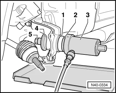
Pressing in wheel hub
Perform further installation in reverse order, paying attention to the following:
=> Brake System; Repair Group 46 Tightening torque
1) Replace nut | |||||||