audi Workshop Repair Guides

Audi Workshop Service and Repair Manuals

Vehicles with top-mounted vane pump > < Removing and installing vane pump
Running gear, Front-wheel drive and four-wheel drive
Removing and installing vane pump
Vehicles with bottom-mounted vane pump
 
W00-0079

Special tools and workshop equipment required

  • ◆ Hose clamps 3094

 
W00-0464
  • ◆ Hose clamp pliers V.A.G 1921
  • ◆ Drip tray
 
A10-0515

Removing

Note:

The following description relates to removal on Audi S3. Certain operations are not required for less powerful engines.

  • ‒ → Remove engine cover -arrows- and cover in front of intake manifold.

 
A10-1164
  • ‒ → Screw out bolt -arrow- and remove cover over expansion tank.
 
A10-1251
  • ‒ → If fitted, unplug connector at secondary-air inlet valve -N112 -arrow-.

 
A26-0490
  • ‒ → Unplug connector -arrow- at exhaust gas temperature sender 1 -G235.
 
A10-0442
  • ‒ → Remove air pipe -arrows-.

 
A13-0083

Note:

Before removing, mark direction of ribbed belt with chalk or felt-tipped pen. Running a used belt in the opposite direction could destroy it.

  • ‒ → Swivel tensioner in direction of arrow to slacken off ribbed belt.
  • ‒ Detach ribbed belt.
 
A13-0072
  • ‒ → Lock tensioner with mandrel ø4.5 mm, approx. 55 mm long, or using special tool 3090.

 
A10-1256
  • ‒ → Remove centre noise insulation -arrows-.
 
A10-1152
  • ‒ → Detach power steering pipe at cross-piece -arrows-.

 
A10-0461
  • ‒ → Unscrew cross-piece on left...
 
A10-0460
  • ‒ → ...and right from longitudinal members; unscrew both hoses to charge-air cooler.
  • ‒ Remove cross-piece.

 
A10-1252
  • ‒ Place drip tray beneath vane pump.
  • ‒ → Unscrew pulley -1- of vane pump whilst providing support with mandrel.
  • ‒ Use hose clamps 3094 to pinch off both hydraulic pipes to vane pump.
 
A10-0920
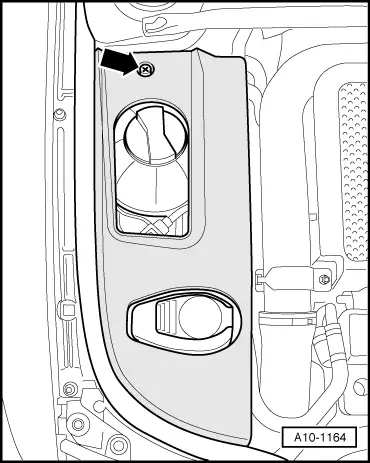
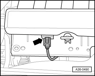
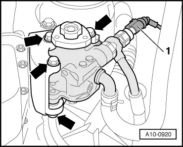
  • ‒ → Unplug connector -1- at power-assisted steering pressure switch
    -F88.
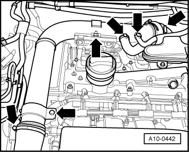
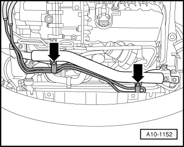
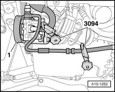
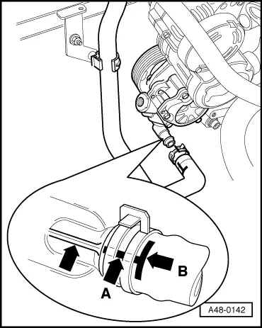
  • ‒ Detach hydraulic hoses at vane pump.
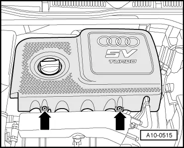
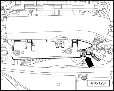
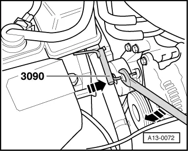
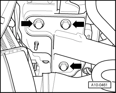
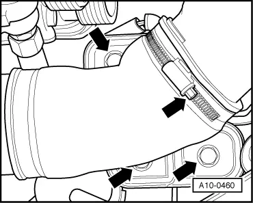
  • ‒ Unscrew vane pump from bracket -arrows-.

Installing

Install in reverse order, paying attention to the following:

Notes:

  • ◆ Replacement pumps are supplied without fluid fill. Prior to installation they are therefore to be filled with hydraulic fluid G 002 000 and cranked by hand to avoid the possibility of noise whilst driving or pump damage.
  • ◆ Contact surfaces and threads on either side of vane pump must be free from paint.
  • ◆ Hydraulic fluid drained off is not to be re-used.
  • ◆ Replace sealing rings.
 
A48-0142
  • ‒ → Fit spring clip and suction hose as shown.
  • ‒ Longitudinal mark -A- at suction hose must be aligned with seam at pump.
  • ‒ Do not fit spring clip beyond transverse mark -B-.
  • ‒ Install cross-piece .

Tightening torques

Component

Nm

Vane pump for power steering to bracket for ancillaries


23

Pulley to vane pump

23

Banjo bolt to vane pump

38

Pressure switch to banjo bolt

15

Vehicles with top-mounted vane pump > < Removing and installing vane pump