audi Workshop Repair Guides

Audi Workshop Service and Repair Manuals

Assignment of contacts at multi-pin connectors at dash panel insert - as of Model Year 1998 > < Multi-pin connectors at dash panel insert
Electrical system
Dash panel insert - up to Model Year 1999
Assignment of contacts at multi-pin connectors at dash panel insert - Model Year 1997
 
A90-0048

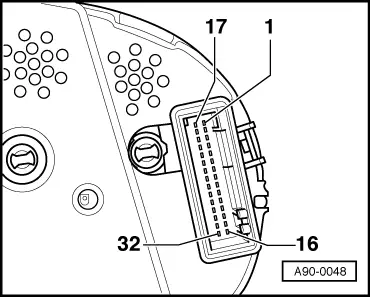
Blue 32-pin connector

  •     1 -    → Terminal 15
  •     2 -    Right turn signal indicator
  •     3 -    Speedometer output 1
  •     4 -    Not used
  •     5 -    Fuel-gauge sender
  •     6 -    Airbag
  •     7 -    Terminal 31 (sensor earth)
  •     8 -    Coolant temperature
  •     9 -    Terminal 31 (load earth)
  •     10 -    Oil pressure switch
  •     11 -    Engine-speed signal
  •     12 -    Terminal 61
  •     13 -    Glow period warning lamp or CAT
  •     14 -    Rear fog light
  •     15 -    Not used
  •     16 -    Trailer turn signal indicator
 
A90-0048
  •     17 -    → Main beam
  •     18 -    Left turn signal indicator
  •     19 -    ABS
  •     20 -    Terminal 58d
  •     21 -    Driver's door contact
  •     22 -    Coolant low
  •     23 -    Terminal 30
  •     24 -    Terminal 31 (load earth)
  •     25 -    K-wire
  •     26 -    Right parking light
  •     27 -    Left parking light
  •     28 -    Speedometer input
  •     29 -    Brake fluid level/pressure
  •     30 -    S-contact
  •     31 -    Belt buckle
  •     32 -    TCS (not used at present)
 
A90-0049

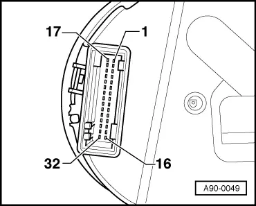
Green 32-pin connector

  •     1 -    → Transponder screen
  •     2 -    Transponder coil
  •     3 -    Not used
  •     4 -    Not used
  •     5 -    W-wire
  •     6 -    Tailgate/boot lid (midline version only)
  •     7 -    Brake pad (not used at present)
  •     8 -    Input for external buzzer actuation (not used at present)
  •     9 -    Input for external gong actuation (not used at present)
  •     10 -    Tank warning output signal for engine control unit (not used at present)
  •     11 -    Standing time output
  •     12 -    Air conditioner shutoff
  •     13 -    Parking brake
  •     14 -    Tailgate/boot lid (highline version only)
  •     15 -    Side light
  •     16 -    Not used
 
A90-0049
  •     17 -    → Transponder coil
  •     18 -    Not used
  •     19 -    Not used
  •     20 -    Not used
  •     21 -    Not used
  •     22 -    Not used
  •     23 -    Not used
  •     24 -    Not used
  •     25 -    Not used
  •     26 -    Ambient temperature
  •     27 -    Not used
  •     28 -    Not used
  •     29 -    Terminal 58d (output signal from photosensor)
  •     30 -    Speedometer output 2
  •     31 -    Selector lever position display
  •     32 -    Not used
 
A90-0050

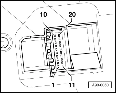
Red 20-pin connector

  •     1 -    → Consumption signal
  •     2 -    Not used
  •     3 -    Not used
  •     4 -    Not used
  •     5 -    Ambient temperature
  •     6 -    Selector lever position display
  •     7 -    Not used
  •     8 -    Not used
  •     9 -    Washer fluid
  •     10 -    Hydraulic pressure
  •     11 -    On-board computer/reset
  •     12 -    Clock signal for radio frequency display
  •     13 -    Data signal for radio frequency display
  •     14 -    On-board computer/left
  •     15 -    Enable signal for radio frequency display
  •     16 -    Reversing light/dipped beam (lamp check)
  •     17 -    Glow plug relay (with diesel engine only, undervoltage monitoring in dash panel insert is suppressed during glow period)
  •     18 -    On-board computer/right
  •     19 -    Brake light
  •     20 -    Not used

Assignment of contacts at multi-pin connectors at dash panel insert - as of Model Year 1998 > < Multi-pin connectors at dash panel insert