
A3 Mk1
|
Self-diagnosis of dash panel insert with Long Life Service as of Model Year 2000
Checking data exchange between control units
Notes:
Checking bus system If fault table indicates that data exchange on bus should be checked. Requirements:
Attention:
Heed safety precautions => Page 01-1. |
 |
|||||||||
|
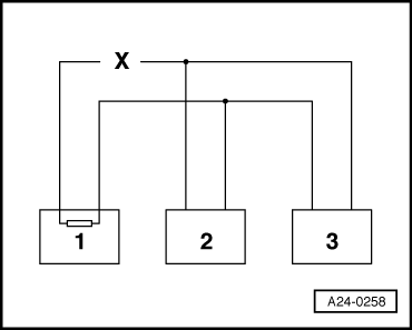
Example 1: Faults entered in fault memories reveal that control unit 1 has no link with control units 2 and 3.
=> Current Flow Diagrams, Electrical Fault-finding and Fitting Locations binder
|
 |
||||||||||||||||||
|
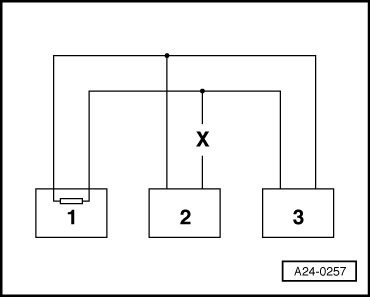
Example 2: Faults entered in fault memories reveal that control unit 2 has no link with control units 1 and 3.
=> Current Flow Diagrams, Electrical Fault-finding and Fitting Locations binder
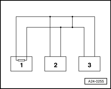
Example 3: Faults entered in fault memory reveal that none of the control units can transmit or receive.
|
 |
|
=> Current Flow Diagrams, Electrical Fault-finding and Fitting Locations binder |
 |
|
=> Current Flow Diagrams, Electrical Fault-finding and Fitting Locations binder If cause of "Drive train data bus defective" fault, for example, is not found in bus wires, check whether one of the control units is responsible for the problem. Test requirement:
All control units using CAN bus for communication still disconnected; ignition off.
|
 |
|
|
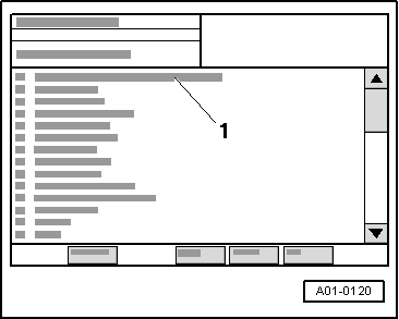
→ Display on VAS 5051:
|