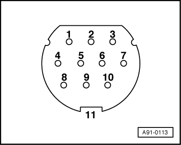
audi Workshop Repair Guides

Audi Workshop Service and Repair Manuals

Connectors at navigation interface R94 > < Connectors at operating electronics control unit, navigation J402
Contact assignment of multi-pin connectors
  Note!
Contacts not listed are not used.
   
20-pin connector I
1 - Rear left signal
2 - Rear right signal
3 - Signal earth
4 - Front left signal
5 - Front right signal
6 - Switched positive (amplifier/BOSE amplifier)
7 - Telephone (AF +)
11 - Remote control/steering wheel (up to MY 01)
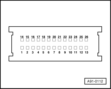
12 - Telephone (AF -)
13 - CD bus data in (CD changer)
14 - CD bus data out (CD changer)
15 - CD bus clock (CD changer)
16 - Permanent positive (CD changer)
17 - Switched positive (CD changer)
18 - Earth (CD changer)
19 - Left signal (CD changer)
20 - Right signal (CD changer)
  A90-0014
8-pin connector II
3 - Front right loudspeaker (+)
4 - Front right loudspeaker (-)
5 - Front left loudspeaker (+) (with BOSE hands-free loudspeaker +)
6 - Front left loudspeaker (-) (with BOSE hands-free loudspeaker -)
Connections with BOSE sound system up to MY 01
  A90-0014
8-pin connector III
1 - GALA (vehicle speed signal)
2 - AF mute (from telephone)
3 - K-wire (diagnosis)
4 - S-contact (terminal 86s)
5 - SAFE (permanent positive; anti-theft protection) (up to MY 01)
6 - Switch illumination (terminal 58s)
7 - Battery + (terminal 30)
8 - Earth (terminal 31)
  A90-0014
11-pin connector (TV tuner)
1 - AF earth
2 - AF left
3 - AF right
4 - Video signal
5 - Video earth
6 - PAL /NTSC
7 - Monitor on
8 - B in
9 - G in
10 - R in
11 - Screen earth
  A91-0113
26-pin connector (navigation system connection)
1 - Anti-theft alarm earth
4 - Terminal 15
5 - Left speed sensor input (ABS)
13 - CAN bus High (Bosch)
17 - Reversing light switch
18 - Right speed sensor input (ABS) (up to MY 01)
26 - CAN bus Low (Bosch)
  A91-0112

Connectors at navigation interface R94 > < Connectors at operating electronics control unit, navigation J402