audi Workshop Repair Guides

Audi Workshop Service and Repair Manuals

Servicing gearbox housing > < Assembly sequence - gearbox with circlip A for input shaft sealing cap
Installing
Installing
l  A new grooved ball bearing has been pressed onto the input shaft → Item.
   
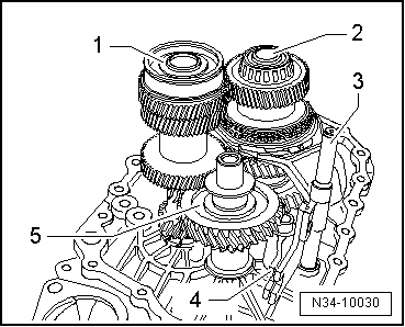
–  Insert input shaft -1-, output shaft for 5th and 6th gear -2- together with selector rod -3-, selector fork -4- and reverse shaft -5-.
  N34-10030
–  Then install differential -1-.
  Note
A second mechanic is required for installing the shafts in the clutch housing.
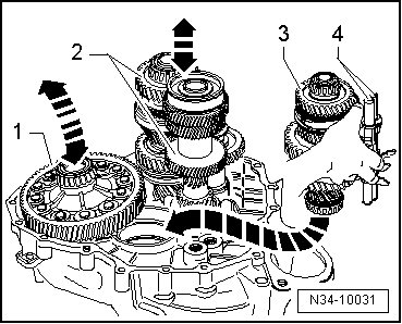
–  Take 1st - 4th gear output shaft -3- with selector rods -4- in your right hand as illustrated.
–  Lift differential slightly with your left hand.
–  At the same time, have the second mechanic lift the input shaft and output shaft for 5th, 6th and reverse gear -2- slightly, together with the reverse shaft.
–  Now insert 1st - 4th gear output shaft in direction of -arrow-.
l  The teeth of the input shaft, output shafts and final drive gear/differential must mesh.
–  Now, together with second mechanic, locate shafts and differential in their bearing seats.
  N34-10031
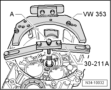
–  Secure support bridge -30-211A- for input shaft to clutch housing.
  Note
Illustration shows clutch housing turned through 180° for clarity.
–  Screw in bolt -A- until input shaft lifts slightly.
  N34-10032
Grooved ball bearing for input shaft will fit into gearbox housing in one position only.
The grooved ball bearing and the bearing mounting are flattened on one side.
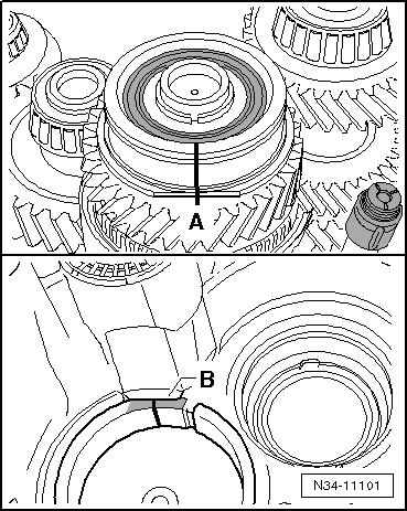
l  If sides are flattened -A- and -B-, washers → Anchor must not be fitted.
l  Flattened sides -A- on grooved ball bearing and bearing mounting -B- in gearbox housing must be aligned.
–  Mark flattened sides with paint.
–  Copy markings onto top area of grooved ball bearing and top area of bearing mounting on gearbox housing (⇒ next illustration).
–  Using hot air blower -V.A.G 1416-, heat area around seat of input shaft ball bearing in gearbox housing for approx. 10 minutes to approx. 100°C.
  Note
t  Heating is necessary to ensure that grooved ball bearing is not damaged when installing gearbox housing.
t  Apply sealing paste -AMV 188 200 03- evenly to sealing surface of clutch housing.
  N34-11101
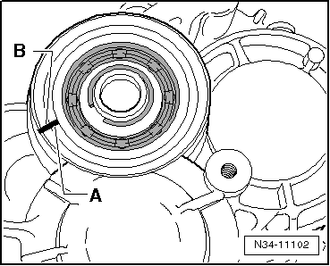
t  Align marking -A- on grooved ball bearing with marking -B- on gearbox housing and fit gearbox housing.
  N34-11102
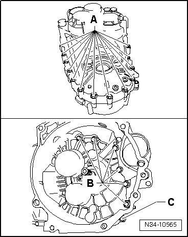
–  Fit gearbox housing and tighten new bolts -A-, -B- and -C- to specified torque.
Allocation of bolts:
A - Bolt with captive washer
B - Bolt without washer
C - Bolt with captive washer
  N34-10565
–  Install circlip -1- for input shaft grooved ball bearing.
–  Attach support bridge -30 - 211 A- for input shaft.
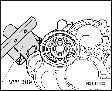
–  If stop sleeve for selector shaft has been removed, drive it in now → Fig. (drive in until tool reaches stop).
–  Turn gearbox on assembly stand so that opening for selector shaft faces up.
  N34-10033
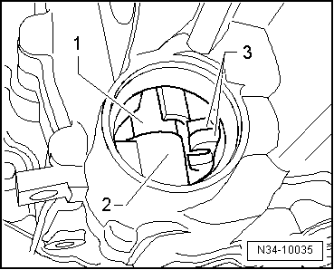
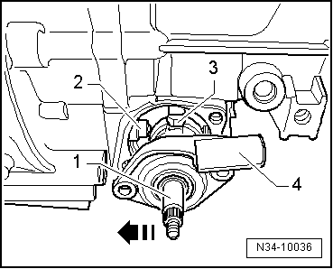
–  Insert selector shaft -1- into bottom mounting -2- and into selector forks -3-.
  Note
The sealing cap is removed to give a better illustration.
  N34-10035
–  Now push selector shaft -1- against stop sleeve -2- in direction of -arrow- and run selector finger -3- down through selector forks and onto stop.
l  Selector mechanism cover -4- should be parallel to joint surface on gearbox housing.
l  Selector shaft should move up and down easily (gate selector movement).
  Note
If the selector mechanism cover is not parallel with the joint surface, the selector shaft is not seated in its bottom mounting.
  N34-10036
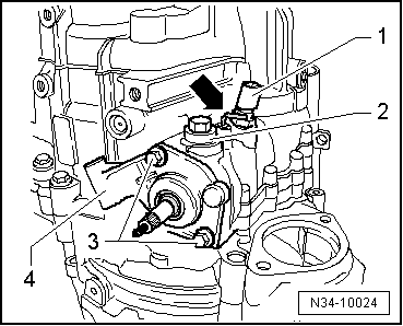
–  Tighten bolts -3- for selector mechanism cover -4-.
–  Screw in locking bolt -2-; angled rod -arrow- must be released.
–  Install reversing light switch -F4--1-.
–  Install flange shafts together with springs, thrust washers and tapered rings.
  N34-10024
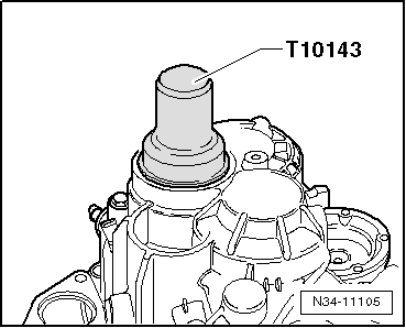
–  Drive sealing cap into gearbox housing onto stop.
  N34-11105
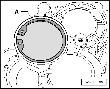
–  Secure sealing cap with circlip -A- (from gearbox manufacturing date approx. 21 01 8 onwards).
  N34-11100

Servicing gearbox housing > < Assembly sequence - gearbox with circlip A for input shaft sealing cap