
A3 Mk2
| Removing gearbox on vehicles with 2.0 ltr. TDI engine (common rail) |

| Special tools and workshop equipment required |
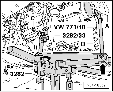
| t | Adapter -VW 771/40- |
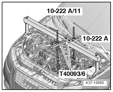
| t | Support bracket -10-222A- |
| t | Rack -10 - 222 A /1- |
| t | Hook -10 - 222 A /11- |
| t | Engine and gearbox jack -V.A.G 1383 A- |
| t | Adapter -T40093/6- |

| t | Stepladder -VAS 5085- |
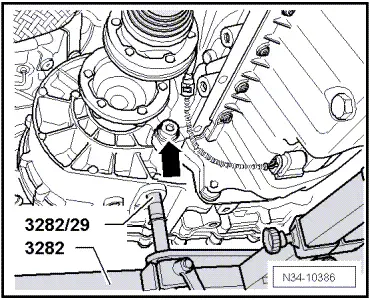
| t | Gearbox support -3282- |
| t | Adjustment plate -3282/33- |
| t | Pin -3282/29- |
| t | Adjustment plate -3282/52- |
| t | Safety support -3282/59- |
| t | Torque wrench -V.A.G 1331- |
| t | Torque wrench -V.A.G 1332- |
|
|
|
|
|
|
|
 Caution
|
|
|
|
|
|
|
|
|
|
|
|
|
|
|
|
|
|
 Note
Note
|
|
|
|
|
|
|
|
|
|
|
|
|
|
|
|
|
|
|
|
Note
|
|
|
|
|
|
|
|
|

|
Note
|
|
Note |
|
|
|
|
|
|
|
Note
|
|
|
|
|
|
|
|
|
|
|
|
|
|
|
|
Note
|
|
|
|
|
|
|
|
|
|
|
|