
A3 Mk2
| Removing gearbox (vehicles with 4-cylinder 2.0 ltr. TFSI engine) |

| Special tools and workshop equipment required |
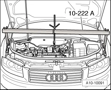
| t | Support bracket -10 - 222 A- |
| t | Rack -10 - 222 A /1- |
| t | Engine and gearbox jack -V.A.G 1383 A- |
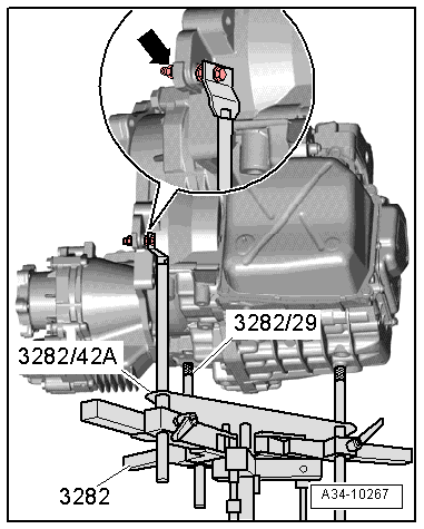
| t | Gearbox support -3282- |
| t | Shackle -10 - 222 A /12- |
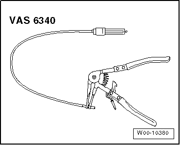
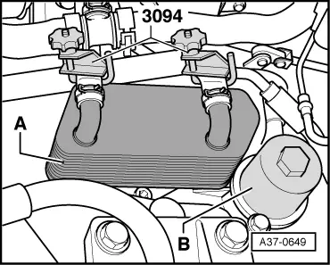
| t | Hose clamps, up to 25 mm -3094- |
|
|
|
|
|
|
|
|
|
|
 Note
Note
|
|
Note
|
|
|
|
|
|
|
|
 Caution
|
|
Note
|
|
|
|
Note
|
|
|
|
Note
|
|
|
|
|
|
Note
|
|
Note
|
|
|
|
|
|
|
|
Note
|
|
Note
|
|
Note
|
|
|
|
|
|
|
|
|
|
Note
|
|
|
|
|
|
|

|
|
|