Audi Workshop Service and Repair Manuals
HOME
FEATURES
MENU
INDEX
ABOUT US
Removing and installing exhaust gas temperature sender 3G495 >
< Exhaust gas temperature control - exploded view
A3 Mk2
Power unit
4-cylinder TDI engine (2.0 ltr. 4-valve common rail), mechanics
Exhaust system
Exhaust gas temperature control (vehicles with engine codes CBAA, CBAB, CBBB)
Removing and installing exhaust gas temperature sender 1G235
Removing and installing exhaust gas temperature sender 1G235
Removing and installing exhaust gas temperature sender 1 -G235-
Removing
–
Unplug electrical connector
-3-
for exhaust gas temperature sender 1 -G235- and move electrical wiring clear.
Note
Disregard
-items 1, 2, 4 and 5-
.
Note
The connection can be accessed from below.
–
Unscrew exhaust gas temperature sender 1 -G235-
-item 1-
from exhaust manifold.
Note
Disregard
-arrows-
.
Installing
Installation is carried out in the reverse order; note the following:
l
Tightening torque
→ Chapter „Exhaust gas temperature control - exploded view“
Note
t
Coat threads of exhaust gas temperature sender with high-temperature paste; for high-temperature paste refer to
→ Electronic parts catalogue
.
t
Fit all cable ties in the original positions when installing.
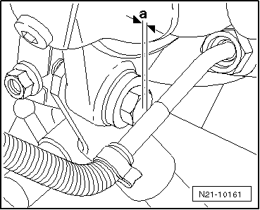
Installation position of exhaust gas temperature sender -G235-:
l
The angled part of the pipe must have a clearance of
-a-
= 3 … 5 mm from the bolt on the turbocharger support.
Power unit
4-cylinder TDI engine (2.0 ltr. 4-valve common rail), mechanics
Exhaust system
Exhaust gas temperature control (vehicles with engine codes CBAA, CBAB, CBBB)
Removing and installing exhaust gas temperature sender 1G235
Removing and installing exhaust gas temperature sender 3G495 >
< Exhaust gas temperature control - exploded view
 Note
Note
Note
Note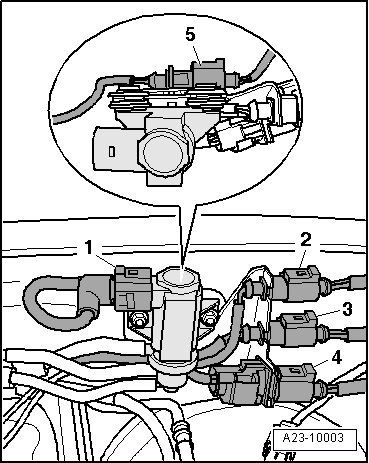 Note
Note
Note
Note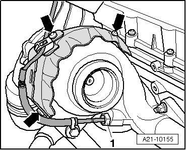
 Note
Note
Note
Note
Note
Note
Note
Note