audi Workshop Repair Guides

Audi Workshop Service and Repair Manuals

Renewing vacuum unit with position sender for charge pressure positionerG581 > < Turbocharger - exploded view
Removing and installing turbocharger
Special tools and workshop equipment required
   
t  Hose clip pliers -VAS 6340-
Removing
–  Observe rules for cleanliness → Chapter.
  Caution
If the turbocharger has suffered mechanical damage (e.g. damaged compressor wheel), it is not sufficient merely to fit a new turbocharger. The following work must be performed in order to avoid further damage:
t  Check air cleaner housing, air filter element and air hoses for dirt and foreign particles.
t  Check the entire charge air system (including the charge air cooler) for foreign matter.
t  If foreign matter is found in the charge air system, clean all relevant ducts and hoses and renew charge air cooler if necessary.
–  Remove particulate filter → Chapter.
  W00-10380
–  Remove air cleaner housing → Rep. gr.23.
  A23-10236
–  Press release tabs and disconnect crankcase breather hose -1- from cylinder head cover.
–  Move clear vacuum hoses -arrows- at air pipe.
–  Loosen hose clip -2- and detach air pipe.
  A21-10337
–  Detach heat shield sleeve.
–  Unplug electrical connector -1- at position sender for charge pressure positioner -G581-.
–  Detach vacuum hose -2- from vacuum unit of turbocharger.
–  Disconnect vacuum hose -3-.
  A21-10338
–  Unplug electrical connector -3- for exhaust gas temperature sender 1 -G235- and move electrical wiring clear.
  Note
Disregard -items 1, 2, 4 and 5-.
  A23-10003
–  Remove bolts -arrows-.
–  Using removal lever -80 - 200-, move clear electrical wiring and hoses at air pipe (left-side).
–  Release hose clip -3- and push air pipe (left-side) from turbocharger towards the left.
  Note
Disregard -items 1, 2, 4 and 5-.
  A19-10641
–  Unscrew oil supply line from connection on turbocharger. To do so, counterhold at hexagon flats with an open-end spanner and slacken union nut -3-.
  Note
Disregard -items 1, 2-.
  A15-10634
–  Remove nuts -arrow- for coupling rod on anti-roll bar on both sides.
  A10-1141
–  Unscrew nuts -arrows- for swivel joint (right-side).
–  Detach swivel joint from wishbone (right-side).
  A40-0228
–  Pivot drive shaft (right-side) towards the front.
–  Tie up drive shaft to longitudinal member -arrow-.
  Note
Take care not to damage the surface coating of the drive shaft.
  A10-10028
–  Unscrew nuts -1- and detach heat shield (left-side) from exhaust manifold.
–  Remove nuts -2- and bolts -3-, and detach exhaust gas recirculation pipe.
  A21-10153
–  Remove bolts -1, 2- and banjo bolt -3-.
–  Detach support for turbocharger with oil return pipe.
  A21-10088
–  Remove bolts -arrows- and detach turbocharger with exhaust manifold from cylinder head.
  A21-10154
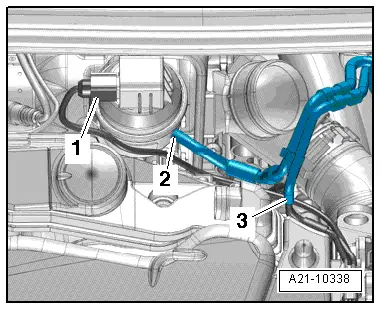
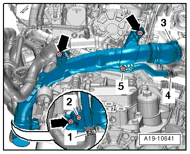
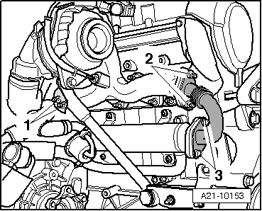
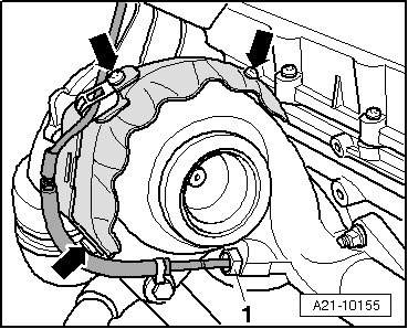
–  Move clear electrical wiring for exhaust gas temperature sender 1 -G235--item 1-.
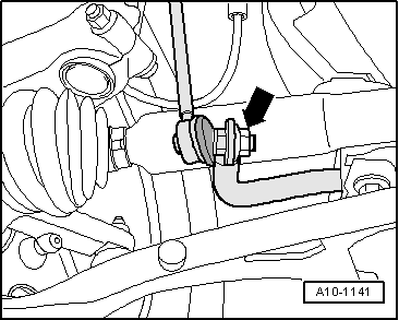
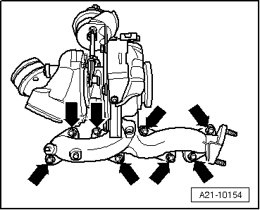
–  Remove bolts -arrows- and detach heat shield.
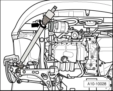
–  Take out turbocharger with exhaust manifold from below, at the same time pushing engine/gearbox assembly slightly forwards.
Installing
Installation is carried out in the reverse order; note the following:
l  Tightening torques → Chapter „Turbocharger - exploded view“
  Note
t  Renew seals, gaskets, O-rings and self-locking nuts.
t  Fill turbocharger with engine oil at connection for oil supply line.
t  Hose connections and air pipes and hoses must be free of oil and grease before assembly.
t  Secure all hose connections with the correct type of hose clips (same as original equipment) → Electronic parts catalogue.
t  To ensure that the air hoses can be properly secured at their connections, spray rust remover onto the worm thread of used hose clips before installing.
t  After installing the turbocharger, allow the engine to idle for approx. 1 minute without pressing the accelerator to ensure that the turbocharger is supplied with oil.
t  Fit heat insulation sleeves in the original positions when installing.
–  Install exhaust system and align free of stress → Chapter.
–  Install wishbone and coupling rod → Rep. gr.40.
–  Install air pipe (left-side) → Chapter.
–  Install air cleaner housing → Rep. gr.23.
–  Install particulate filter → Chapter.
–  Check oil level → Booklet808.
  A21-10155

Renewing vacuum unit with position sender for charge pressure positionerG581 > < Turbocharger - exploded view