audi Workshop Repair Guides

Audi Workshop Service and Repair Manuals

TDI injection and glow plug system (4-cyl. 2.0 ltr. unit injector, 4-valve) > < Checking exhaust gas recirculation change-over
Removing and installing exhaust gas recirculation cooler
Special tools and workshop equipment required
   
t  Hose clamps for hoses up to 25 mm Ø -3094-
  W00-0079
t  Hose clip pliers -VAS 6340-
  W00-10380
Removing
–  Lift engine cover panel at sides -arrows 1- and pull off towards front -arrow 2-.
  A10-1855
–  Detach the hoses/lines -1 ... 3- from air pipe.
–  Remove air pipe by lifting retaining clips -arrows- slightly.
  Note
Leave coolant hose -1- and fuel lines -2- and -3- connected.
  A10-1838
–  Unplug electrical connector -2- at air mass meter -G70-.
–  Detach vent hose -1- and air hose -3-.
  A10-1667
–  Detach electrical connector -arrow- at intake manifold flap motor -V157-.
–  Unscrew bolts -1 ... 3- and detach intake manifold flap motor -V157-.
  A10-1836
–  Disconnect vacuum hose -3- at exhaust gas recirculation valve -N18-.
–  Detach pipe -4- for crankcase breather at air pipe.
–  Release hose clip -1- at turbocharger using hose clip pliers -VAS 6340-.
–  Move the vacuum hoses clear -arrow-.
–  Unscrew bolts -2- and -5- and remove air pipe.
  A10-1837
–  Clamp off coolant hoses -1- and -2- at exhaust gas recirculation cooler using hose clamps -3094- and detach.
  A15-0793
–  Clamp off coolant hoses -1- and -2- using hose clamps -3094- and detach.
  A15-0794
–  Detach hose connection carrier -2- at solenoid valve block by releasing retaining tab.
–  Detach vacuum hose -1- at non-return valve for brake servo.
  A10-1668
–  Detach vacuum hose -arrow- going to brake servo at tandem pump.
  A10-1851
–  Unbolt engine lifting eye at rear on cylinder head -arrow-.
  A15-1032
–  Unbolt connecting pipe beneath change-over flap for exhaust gas recirculation -arrows-.
  A15-1033
–  Remove bolts -arrows-.
  A15-1031
–  Unbolt exhaust gas recirculation cooler (with change-over flap) from intake manifold -arrows- and remove.
Installing
Installation is carried out in the reverse order; note the following:
  Note
t  Renew gaskets, seals and self-locking nuts.
t  Note the installation position of intake manifold gasket.
t  Charge air system must be free of leaks.
t  Hose connections and hoses for charge air system must be free of oil and grease before assembly.
t  Secure all hose connections with the correct type of hose clips (same as original equipment) → Parts catalogue.
–  Install air pipes/hoses with plug-in connectors → Chapter.
–  Fill cooling system → Anchor.
Tightening torques
  A15-1035
ComponentNm
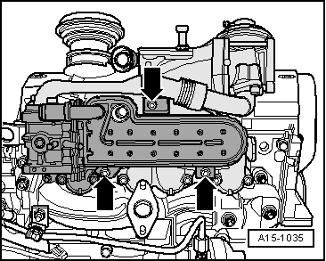
Exhaust gas recirculation cooler to intake manifold10
Bracket to intake manifold10
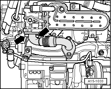
Connecting pipe for exhaust gas recirculation to change-over flap22
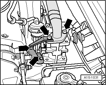
Intake manifold flap motor -V157- to intake manifold10
Engine lifting eye to cylinder head22


TDI injection and glow plug system (4-cyl. 2.0 ltr. unit injector, 4-valve) > < Checking exhaust gas recirculation change-over