
A3 Mk2
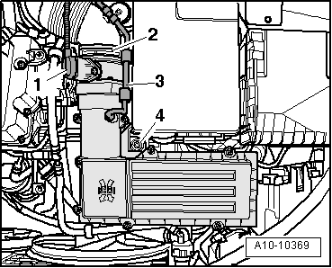
| Removing and installing oil filter bracket with oil cooler |

| Special tools and workshop equipment required |
| t | Used oil collection and extraction unit -V.A.G 1782- |
| t | Hose clip pliers -V.A.G 1921- |
| t | Assembly tool -T10118- |
|
|
|
|
|
|
|
|
|
|
|
|
|
|
|
|
 Note
Note
|
|
|
|
|
|
|
|
|
|
Note
|
|
| Component | Nm | |||||
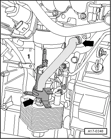
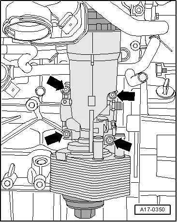
| Oil filter bracket to cylinder block | 14 + 90° 1)2) | |||||
| Guide tube for oil dipstick to: | Oil filter bracket | 10 | ||||
| Lifting eye | 10 | |||||
| Bracket for wiring harness to oil filter bracket | 10 | |||||
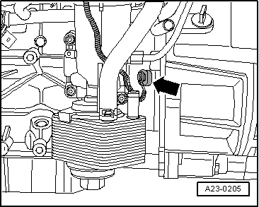
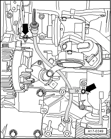
| Oil pressure switch to oil filter bracket | 20 | |||||
| ||||||